Lab-13 Shift Registers
Objective:
- To explain the operation of a serial shift register.
- To describe the function of a shift register behaving as a ring counter.
Components:
2 - 7474
4 - LEDs
6 - 330Ω resistors
2 – DIP switches
Bag of wires
Breadboard
BNC-to-BNC
BNC-to-Alligator
1 – Banana to Alligator
1 – Oscilloscope probe
1 – T connector
Background:
Among the most important sequential circuits that are widely used in digital systems are registers. A 1-bit register requires one flip-flop, so an array of these flip-flops is required to store binary information either in 1, 4, 8, 16 or 32 bits of data accordingly.
Registers can both receive and transmit data either in serial (one-bit at a time) or in parallel (simultaneously) form. They can be classified depending upon the way in which data are entered and exited. There are four modes of operation:
- serial in, serial out (SISO)
- serial in, parallel out (SIPO)
- parallel in, serial out (PISO) and
- parallel in, parallel out (PIPO).
A register designed to transfer any given data from one flip-flop to another is commonly known as a Shift Register. The data bits are shifted in the flip-flops with the occurrence of clock pulses either in the right direction (right-shift registers) or in the left direction (left- shift register) before sending it back out again. A register that can shift data in both ways is called a bi-directional shift register.
Procedure:
PART A : Shift Register Operation (SISO)
Construct a 4-bit shift register using D Flip-flops
Connect all the clear/reset inputs together and connect them to a switch (switch B)
Connect another switch (switch A) to the D input of the first flip-flop
Each switch is connected at one end to GND, while the other end of the switch is connected to a 330 ohm pull-up resistor to 5V, which is also connected to the input of the chip (D or clear/reset, respectively)
Connect a function generator to the Clock inputs (square wave, 3V amplitude, 1.5V offset, 1 Hz frequency, Hi-Z load)
Connect all the preset inputs together and to a common 330 ohm resistor pulled up to 5V.
Connect each Q output to a separate LED. The output will be connected to a 330 ohm series resistor, whose other end will be connected to the anode of the LED (longer lead). The cathode will be connected to GND.
(Take note of the components assigned to the DATA INPUT, Clock, CLEAR / RESET pins and the output pins of each D flip-flop, QA, QB, QC and QD respectively).
- Set your switch A to LO for initial stage and Switch B to HI.
Switch B is to reset your circuit. If any LEDs are ON, reset your system by setting switch B to low (GND) and then set it back to high again. The reset mode for the D flip-flop requires an active low input pulse.
- Assign your Clock input to the function generator that generates a square wave with a frequency of 1 Hz. Connect the waveform to your system.
As explained earlier, the shift register operation is based on a clock pulse from the square wave form. One clock pulse is defined as or depending on the mode of edge-triggered operation of the flip-flop. For the D Flip flop in this lab, you will be triggering the flip-flop on the rising edge.
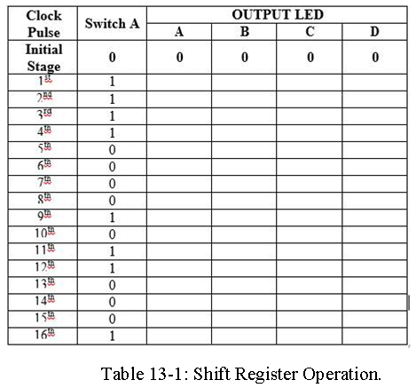
- Refer to Table 1. Set your initial Data Input value to HI at the first clock pulse. Record your output values.
Complete Table 13-1 by recording the output values based on the given input values. Demonstrate and verify your operation.
Caution : If your register is too fast to record, you can slow down the frequency to suit your pace. You may need to reset your system so that you can follow the input values you have missed.
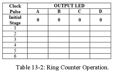
PART B : Ring Counter Operation 1. Reconstruct your existing shift registers into a Ring Counter. Switch A will then be connected to the PRESET (PR) at pin 4 of your first D Flip-flop as your DATA INPUT. Refer to Figure-13.1.

Set your Switch A to LO and Switch B to HI.
Set your pattern generator to square wave with a 1 Hz frequency. Connect the Clock pin to your pattern generator.
Now set your Switch A to LO for a second and wait for LED A to light up before setting Switch A to HI again. (You should only get one LED A that will light up before it is shifted to LED B).
Complete Table 13-2 on what you have observed from your LED outputs. Demonstrate and verify with your instructor upon completion of your system.