Lab-1 Kirchhoff’s Current Law (KCL) and Kirchhoff’s Voltage Law (KVL):
Name: Write down your name
Date: Date of report submission and date of lab performed
Objectives:
- To properly measure the currents and the voltages in a resistive circuit.
- To experimentally verify Kirchhoff’s Current Law (KCL) and Kirchhoff’s Voltage Law (KVL).
Equipment:
Multisim software (National Instruments), breadboard.
Overview:
Build and simulate circuits using Multisim software.
Build circuit in breadboard in the laboratory.
Record results from simulation and from calculations using MS Word into this document (fill in the blanks, indicate yes/no to questions).
Make screen shot (Print-Screen) of each simulating circuit to make image of the circuit with V and I values visible. Paste images into the MS Word file at appropriate place.
Procedure:
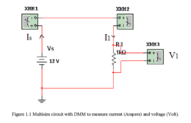
- Open the Multisim software. In Multisim, build circuit 1 as diagrammed in Figure 1.1. The primary components of the circuit are the power supply (Vs) and one resistor (R1). An icon button to add these basic components is near top left of window. The square boxes in the circuit are Indicators to act as a DMM to measure current (Ammeter) or to measure voltage (Voltmeter). An icon button to add Indicators is further to the right from the previous icon button to add basic components. To connect each node with a wire, place the mouse cursor over a node, and press mouse button to start drawing a wire. Label each component and indicator as shown in Circuit 1 by right-clicking on the object and selecting Properties. Feel free to use different values for Vs or R1 than those suggested. Add a ground to the circuit, selecting a top left icon button to add the ground. Add Text to add a “Circuit 1” label near the top and add all the names of the team members. Save circuit in your P/drive or on a thumb drive (so that each team member can have a copy of this file for future reference).
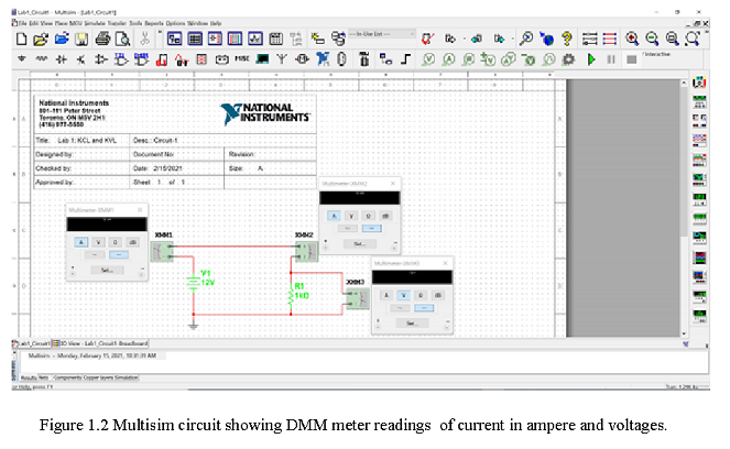
- To run this simulation of this circuit and to have the indicators display the resulting values of I and V, hit the green arrow near the top middle. The simulation will continually run (producing the same result again and again since this is a DC circuit and nothing changes) until the stop button (red square) is pushed. Save the Multisim file after running simulation. Print the circuit.
From this Multisim simulation, write down the values displayed on the indicators.
\(I_s\) = 12 mA___________________
\(I_1\) =12 mA___________________ does \(I_1=I_s\) (yes/no)?
\(V_1\) = 12 V____________________ does \(V_1 = V_s\) (yes/no)?
Make the following Calculations and comparisons (show your work).
\(I1 = (V1/R1) = (12 V/1 k\Omega)\) = 12 mA same value as Multisim (yes/no)?
- With the circuit being simulated with the V and I values displayed, make a screen shot (hit “PrtSc” button, and paste here into this MS Word file.)
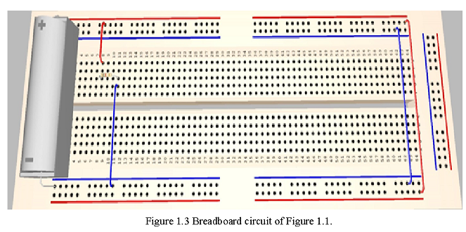
- Construct the circuit on breadboard (please figure below) in the laboratory and write down the similar results as noted in 2.
- Write down the breadboard data as follows:
\(I_s\) = ___________________
\(I_1\) =___________________ does \(I_1=I_s\) (yes/no)?
\(V_1\) = ____________________ does \(V_1 = V_s\) (yes/no)?
Make the following Calculations and comparisons (show your work).
\(I_1 = (V_1/R_1)\) = same value as Multisim (yes/no)?
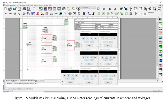
- In Multisim, build circuit 2 as diagrammed. Run the simulation (Green Arrow). Save the Multisim file after running simulation.

From this Multisim simulation, write down the values displayed on the indicators.
\(I_s\) = 2.914 mA
\(I_1\) = 1.714 mA
\(I_4\) = 1.2 mA
\(V_1\) = 1.2 V
\(V_2\) = 7.2 V
\(V_3\) = 3.6 V
\(V_4\) = 12 V
Make the following Calculations and comparisons (show your work)
Theory – Kirchhoff’s Voltage Law (KVL) states that for any continuous loop in a circuit, the sum of the changes in voltage over each component must be equal to zero. \(\sum V = 0\)
\(V_1 + V_2 + V_3 = V_4\)
Provide the equations to illustrate KVL around loops in in this circuit here.
1.2 V + 7.2 V + 3.6 V = 12 V
- Theory – Kirchhoff’s Current Law (KCL): for any node in a circuit, the sum of the currents at a node must be zero.
\[\sum I = 0\] \[I_s = I_1 + I_4\]
Provide the equation to illustrate KCL at the node at the top of the circuit here
2.914 mA = 1.714 mA + 1.2 mA
- With the circuit being simulated with the V and I values displayed, make a screen shot (hit “PrtSc” button, and paste here into this MS Word file.
- Construct the circuit on breadboard (please figure below) in the laboratory and write down the similar results as noted in 6.
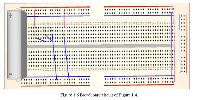
Please note: The above breadboard circuit that I made in Multisim is just a sample circuit for you to follow in the lab. Also, note that I used red wires to make connections from positive end of the power supply and blue wire I used to indicate that it goes to ground of power supply. On the right side of the breadboard I connected both positive ends with a red wire and both negative ends with a blue wire so that you can use the whole breadboard to make much more complicated circuits in the future. Thanks