Lab-6 Capacitive and Inductive Reactances:
Name:
Date:
Objectives:
Determine capacitive reactance (\(X_C\)).
Determine inductive reactance (\(X_L\)).
Materials Needed:
One 10K Ohm Resistor
One 1 µF capacitor
One 2.2 µF capacitor
One 1 mH inductor
One 10 mH inductor
Procedure for Capacitive Reactance:
Build the circuit as shown in Figure 6.1 with \(V_{in}=10 V_{p-p}\), 200 Hz sine wave, R = 10K , and C = 1 \(\mu F\).
Determine the current I (use a voltmeter to measure \(V_R\) across the resistor) by dividing \(V_R\) by the value of R.
Place one probe across the generator and another across the capacitor.
Measure the capacitor voltage (\(V_C\)).
Using I from step 2 and the measured \(V_C\), determine the experimental reactance (\(X_C = V_C/I_C\)).
Calculate the capacitance using the experimental reactance:
\[C= 1/ωX_C= 1/(2πfX_C)\]
Replace the 1 \(\mu F\) capacitor with the 2.2 \(\mu F\) capacitor and repeat steps 1-6, using a 2 KHz frequency.
Calculated Capacitive Reactance:
\[X_{c,calculated}=\frac{1}{\omega C}=\frac{1}{2\pi fC}=\frac{1}{2\pi (200\space Hz) (1\times 10^{-6}F)}=796\Omega\]
Measured Capacitive Reactance (Multisim):
\(V_c\) =0.791 V; \(I_c=V_R/R\) =(9.969 V)/(\(10 \times 10^3\) )=\(0.9969 \times 10^{-3}\) A=0.9969 mA
\[X_{c,multisim)}=\frac{V_c}{I_c} =\frac{0.791 V}{0.9969 \times 10^{-3}A} =793 \Omega\]
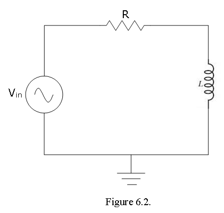
- Procedure for Inductive Reactance:
Build the circuit as shown in Figure 6-2 with \(V_{in}\) =10 \(V_{p-p}\), 1 KHz sine wave, R = 10 K, and L = 10 mH.
Determine the current I (use a voltmeter to measure \(V_R\) across the resistor) by dividing \(V_R\) by the value of R.
Place one probe across the function generator and another across the inductor.
Measure the inductor voltage (\(V_L\)).
Using I from step 2 and the measured \(V_L\), determine the experimental reactance (\(X_L = V_L/I_L\)).
Calculate the inductance using the experimental reactance:
\(L=\frac{X_L}{(2πf)} = \frac{X_L}{ω}\)
Replace the 10 mH inductor with the 1 mH inductor and repeat steps 1-6, using a 2 K Hz frequency.