Lab-2 DC Voltage and Current Measurement:
Name: ____________________________
Date: ____________________________
Objectives:
To learn how to construct a circuit on the analog breadboard
To learn how to connect voltmeters and ammeters in a circuit to measure DC voltages and currents.
Equipment and Parts:
Table 2.1 Eqipment and Parts.
| Item | Quantity | Item | Quantity |
|---|---|---|---|
| 68 \(\Omega\) | 1 | 10 \(k\Omega\) | 1 |
| 330 \(\Omega\) resistor | 1 | Breadboard | 1 |
| 2.2 k\(\Omega\) | 1 | Banana/clip | 2 |
| 3.3 k\(\Omega\) | 1 | Bag of wires | 1 |
| 6.8 k\(\Omega\) | 1 | – | – |
| Power supply | 1 | Digital Multi Meter(DMM) | 1 |
Outcomes:
- Enter the measured results and response to the question in step 3 as the edit to this document. Submit the revised document to Brightspace.
Background:
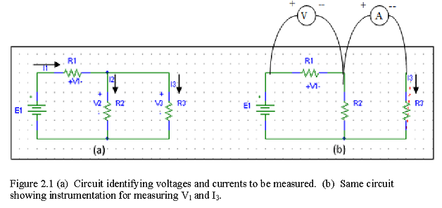
In this experiment, digital multimeter (DMM, on the bench) is used to measure DC voltage and current. When making measurements in a circuit, it is good practice to first connect the circuit without the meters, identify the quantities you want to measure, and then connect the meters accordingly. When connecting a voltmeter in a circuit, as shown as “V” enclosed in a circle in Figure 1, connect the two leads of the voltmeter to the two points where the voltage is to be measured. The red lead (+) is connected to the positive side, and the black ( ) to the negative side. To connect an ammeter in a circuit, as shown as “A” enclosed in a circle in Figure 1, the line carrying the current to be measured must be opened up so that the two open ends are accessible. The two leads of the ammeter are connected to the two open ends, with the current flowing in DMM at the red lead (+). These connections are illustrated in Figure 2.1.
Procedures:
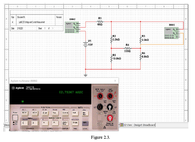
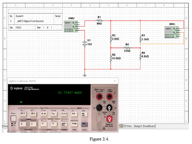
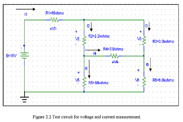
- Construct the circuit as shown in Figure 2-2.
- Use the bench DMM to measure the voltages and currents. Record the measurement in Table 2-2.
Table 2.2 Voltages and currents.
| \(V_1\) | \(V_2\) | \(V_3\) | \(V_4\) | \(V_5\) | \(V_6\) | |
| Simulation (V) | ||||||
| \(V_1\) | \(V_2\) | \(V_3\) | \(V_4\) | \(V_5\) | \(V_6\) | |
| Measured (V) | ||||||
| \(I_1\) | \(I_2\) | \(I_3\) | \(I_4\) | \(I_5\) | \(I_6\) | |
| Simulation (mA) | ||||||
| \(I_1\) | \(I_2\) | \(I_3\) | \(I_4\) | \(I_5\) | \(I_6\) | |
| Measured (mA) |
Make the following Calculations and comparisons (show your work)
Theory – Kirchhoff’s Voltage Law (KVL) states that for any continuous loop in a circuit, the sum of the changes in voltage over each component must be equal to zero.\(\sum V = 0\).
Provide the equations to illustrate KVL around loops in this circuit here.
Theory – Kirchhoff’s Current Law (KCL): for any node in a circuit, the sum of the currents at a node must be zero.
\(\sum I = 0\).
Provide the equation to illustrate KCL at the node at the top of the circuit here.
With the circuit being simulated with the V and I values displayed, make a screen shot (hit “PrtSc” button, and paste here into this MS Word file.