Lab-7 Maximum Power Transfer:
Name:
Date:
Objectives:
To analyze a network and determine the maximum power transfer.
Equipment:
1 – 56Ω fixed resistor, 1 – Decade box, Breadboard, Agilent DMM, 4 – Long leads, Bag of Wires.
Introduction:
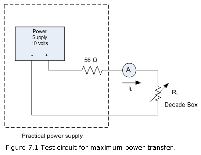
The internal resistance of the bench power supply is very small and therefore it is difficult to obtain accurate results if we try to determine maximum power transfer to a practical load. Consequently, we will simulate a practical source by connecting a 56 Ω resistor in series with the bench power supply. The bench power supply will be considered an ideal source since its internal resistance is negligible when compared to the 56 Ω resistor.
Procedure:
Part I:
Set up the circuit shown in Figure 7.1.
With RL disconnected from the circuit, set the open-circuit voltage to 10 volts (\(V_{oc}\) = 10.0 V) using the digital multimeter.
Set the resistance of the decade box to 150 Ω and connect it into the circuit. Record \(V_L\) and \(I_L\).
\(V_L\) = _______________________
\(I_L\) = _______________________
- Calculate the internal resistance using
\(R_i\) = \(\frac{V_{oc}-V_L}{R_L}\)
\(R_i\) = _______________________
- Now turn off the bench power supply, remove the 56 Ω resistor and measure its value.
\(R_S\) = ___________________________
- The Rs value measured in step 5 should equal \(R_i\). If not repeat steps 2 through 4 and if still does not explain the reason(s).
Part II:
Maximum power into the load occurs when the resistance of the load is equal to the internal resistance of the power source.
Reconnect the 56 Ω resistor as in Part I.
Vary \(R_L\) using the dial settings on the decade box for the values given in the following table and record the corresponding values of \(V_L\) and \(I_L\). Enter the data into an Excel spreadsheet.
| \(R_L\) | 1568 | 784 | 392 | 196 | 112 | 64 | 56 | 49 | 28 | 16 | 8 | 4 | 2 | 0 |
| \(V_L\) | ||||||||||||||
| \(I_L\) | ||||||||||||||
| \(P_L\) |
- Calculate the value of \(P_L\) for each set of readings and plot \(P_L\) against \(R_L\).
Question:
If \(R_L\) were fixed at 10 Ω and \(R_i\) could be varied (for example by using various power supplies from different manufactures), what value of \(R_i\) would you choose so that the 10 Ω load resistor would dissipate maximum power for a given voltage setting of the ideal power supply voltage (\(V_{oc}\))?