Chapter 13 Electromagnetic Waves
Learning Objectives:
In this chapter you will basically learn:
\(\bullet\) Electromagnetic spectrum specifically AM radio, FM radio, television, infrared light, visible light, ultraviolet light, x rays, and gamma rays.
\(\bullet\) The transmission of an electromagnetic wave by an LC oscillator and an antenna.
\(\bullet\) A transmitter with an LC oscillator, with inductance L, capacitance C, and angular frequency \(\omega\), and the emitted wave’s frequency f and wavelength \(\lambda\).
\(\bullet\) The speed of an electromagnetic wave in vacuum.
\(\bullet\) Apply the relationships between an electromagnetic wave’s frequency f, wavelength \(\lambda\), period T, angular frequency \(\omega\), and speed c.
\(\bullet\) An electromagnetic wave consists of an electric component and a magnetic component that are (a) perpendicular to the direction of travel, (b) perpendicular to each other, and (c) sinusoidal waves with the same frequency and phase.
\(\bullet\) The relationship between the speed of light c, the permittivity constant \(\varepsilon_0\), and the permeability constant \(\mu_0\).
\(\bullet\) The relationship between the speed of light c and the ratio of the electric field amplitude E to the magnetic field amplitude B.
\(\bullet\) An electromagnetic wave transports energy with rate of energy transport per unit area is given by the Poynting vector, which is the cross product of the electric field \(\vec E\) and magnetic field \(\vec B\).
\(\bullet\) The EM wave’s intensity I and the electric field’s rms value \(E_{rms}\) and amplitude \(E_m\).
\(\bullet\) For an isotropic source of light, the relationship between the emission power P, the distance r to a point of measurement, and the intensity I at that point.
\(\bullet\) An electromagnetic wave transports momentum and can exert a force and a pressure on a target.
\(\bullet\) Distinguish between polarized light and unpolarized light.
\(\bullet\) Distinguish between a polarizer and an analyzer.
\(\bullet\) Identify the incident ray, the reflected ray, the normal, the angle of incidence, the refracted ray and the angle of reflection.
\(\bullet\) Explain total internal reflection and include the angle of incidence, the critical angle, and the relative values of the indexes of refraction on the two sides of the interface.
\(\bullet\) Explain how unpolarized light can be converted to polarized light by reflection from an interface at Brewster’s angle.
13.1 Electromagnetic Waves: Maxwell’s Rainbow
13.2 The Traveling Electromagnetic Wave Qualitatively
13.3 The Traveling Electromagnetic Wave Qualitatively
13.4 Energy Transport and the Poynting Vector
In a conventional microwave oven we make use of electromagnetic waves to heat up foods that we observe in practice. Also, heat waves come from Sun we can feel during scorching summer. But many of the nuclear radiation we can not even feel can mutate or destroy living cells and cause cancer.
In electromagnetic waves, the amplitude is the maximum field strength of the electric and magnetic fields. The wave energy is determined by the wave amplitude.
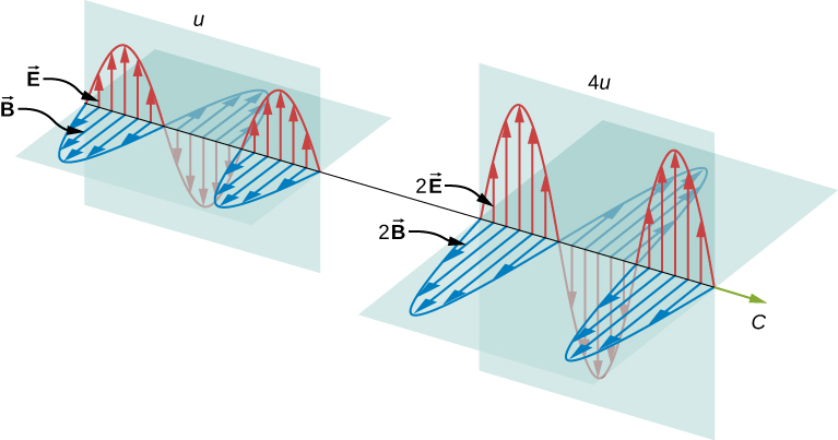
Figure 13.1 Energy carried by a wave depends on its amplitude. With electromagnetic waves, doubling the E fields and B fields quadruples the energy density u and the energy flux.
For a plane wave traveling in the direction of the positive x-axis with the phase of the wave chosen so that the wave maximum is at the origin at t=0, the electric and magnetic fields are given by
\[E_y(x,t)=E_0\cos(kx-\omega t)\]
\[B_z(x,t)=B_0\cos(kx-\omega t).\]
The energy in any part of the electromagnetic wave is the sum of the energies of the electric and magnetic fields. This energy per unit volume, or energy density u, is the sum of the energy density from the electric field and the energy density from the magnetic field. In practice we can create electric energy \(u_E\) using a capacitor and and magnetic energy \(u_B\) an inductor. The combination of these two types of energies will give us the total energy that is carried out by an electromagnetic waves:
\[u(x,t)=u_E+u_B=\frac{1}{2}\epsilon_0E^2+\frac{1}{2\mu_0}B^2.\]
The expression \(E=cB=\frac{1}{\sqrt{\epsilon_0\mu_0}}B\) then shows that the magnetic energy density \(u_B\) and electric energy density \(u_E\) are equal, despite the fact that changing electric fields generally produce only small magnetic fields. The equality of the electric and magnetic energy densities leads to
\[\begin{equation} u(x,t)=u_E+u_B =\frac{1}{2}\epsilon_0E^2+\frac{1}{2}\epsilon_0E^2. \tag{13.1} \end{equation}\]
The energy density moves with the electric and magnetic fields in a similar manner to the waves themselves.
We can find the rate of transport of energy by considering a small time interval \(\Delta t\). As shown in Figure 13.3, the energy contained in a cylinder of length \(c\Delta t\) and cross-sectional area A passes through the cross-sectional plane in the interval \(\Delta t\).
Figure 13.3 The energy \(uAc\Delta t\) contained in the electric and magnetic fields of the electromagnetic wave in the volume \(Ac\Delta t\) passes through the area A in time \(\Delta t\).
The energy passing through area A in time \(\Delta t\) is
\[u\times\mathrm{volume}=uAc\Delta t.\]
The energy per unit area per unit time passing through a plane perpendicular to the wave, called the energy flux and denoted by S, can be calculated by dividing the energy by the area A and the time interval \(\Delta t\).
\[S=\frac{\mathrm{Energy~passing~area}~A~\mathrm{in time}~\Delta t}{A\Delta t}=uc=\epsilon_0cE^2=\frac{1}{\mu_0}EB.\]
More generally, the flux of energy through any surface also depends on the orientation of the surface. To take the direction into account, we introduce a vector \(\vec{\mathbf{S}}\), called the Poynting vector, with the following definition:
\[\begin{equation} \vec{\mathbf{S}}=\frac{1}{\mu_0}\vec{\mathbf{E}}\times\vec{\mathbf{B}}. \tag{13.2} \end{equation}\]
The cross-product of \(\vec{\mathbf{E}}\) and \(\vec{\mathbf{B}}\) points in the direction perpendicular to both vectors. To confirm that the direction of \(\vec{\mathbf{S}}\) is that of wave propagation, and not its negative, return to Figure 13.2.2. Note that Lenz’s and Faraday’s laws imply that when the magnetic field shown is increasing in time, the electric field is greater at x than at \(x+\Delta x\). The electric field is decreasing with increasing x at the given time and location. The proportionality between electric and magnetic fields requires the electric field to increase in time along with the magnetic field. This is possible only if the wave is propagating to the right in the diagram, in which case, the relative orientations show that \(\vec{\mathbf{S}}=\frac{1}{\mu_0}\vec{\mathbf{E}}\times\vec{\mathbf{B}}\) is specifically in the direction of propagation of the electromagnetic wave.
The energy flux at any place also varies in time, as can be seen by substituting u from Equation 13.2.11 into Equation 13.3.1.
\[\begin{equation} S(x,t)=c\epsilon_0E_0^2\cos^2(kx-\omega t) \tag{13.3} \end{equation}\]
Because the frequency of visible light is very high, of the order of \(10^{14}~\mathrm{Hz}\), the energy flux for visible light through any area is an extremely rapidly varying quantity. Most measuring devices, including our eyes, detect only an average over many cycles. The time average of the energy flux is the intensity I of the electromagnetic wave and is the power per unit area. It can be expressed by averaging the cosine function in Equation 13.3.3 over one complete cycle, which is the same as time-averaging over many cycles (here, T is one period):
\[\begin{equation} I=S_{\mathrm{avg}}=c\epsilon_0E_0^2\frac{1}{T}\int_0^T\cos^2\left(2\pi\frac{t}{T}\right)dt \tag{13.4} \end{equation}\]
We can either evaluate the integral, or else note that because the sine and cosine differ merely in phase, the average over a complete cycle for ^2is the same as for ^2, to obtain
\[\langle\cos^2\xi\rangle=\frac{1}{2}\left[\langle\cos^2\xi\rangle+\langle\sin^2\xi\rangle\right]\frac{1}{2}\langle1\rangle=\frac{1}{2}.\]
where the angle brackets \(\langle\ldots\rangle\) stand for the time-averaging operation. The intensity of light moving at speed c in vacuum is then found to be
\[\begin{equation} I=S_{\mathrm{avg}}=\frac{1}{2}c\epsilon_0E_0^2 \tag{13.5} \end{equation}\]
in terms of the maximum electric field strength E_0, which is also the electric field amplitude. Algebraic manipulation produces the relationship
\[\begin{equation} I=\frac{cB_0^2}{2\mu_0} \tag{13.6} \end{equation}\]
where B_0 is the magnetic field amplitude, which is the same as the maximum magnetic field strength. One more expression for I_{} in terms of both electric and magnetic field strengths is useful. Substituting the fact that cB_0=E_0,, the previous expression becomes
\[\begin{equation} I=\frac{E_0B_0}{2\mu_0}. \tag{13.7} \end{equation}\]
We can use whichever of the three preceding equations is most convenient, because the three equations are really just different versions of the same result: The energy in a wave is related to amplitude squared. Furthermore, because these equations are based on the assumption that the electromagnetic waves are sinusoidal, the peak intensity is twice the average intensity; that is, I_0=2I.
EXAMPLE 13.3.1: The beam from a small laboratory laser typically has an intensity of about \(1.0\times10^{-3}~\mathrm{W/m}^2\). Assuming that the beam is composed of plane waves, calculate the amplitudes of the electric and magnetic fields in the beam.
Solution: Use the equation expressing intensity in terms of electric field to calculate the electric field from the intensity.
From Equation 13.5.5, the intensity of the laser beam is
\[I=\frac{1}{2}c\epsilon_0E_0^2.\]
The amplitude of the electric field is therefore
\[\begin{eqnarray} E_0&=&\sqrt{\frac{2}{c\epsilon_0}I}=\sqrt{\frac{2}{(3.00\times10^8~\mathrm{m/s})(8.85\times10^{-12}~\mathrm{F/m})}(1.0\times10^{-3}~\mathrm{W/m}^2)}\\&=&0.87~\mathrm{V/m}. \tag{13.8} \end{eqnarray}\]
The amplitude of the magnetic field can be obtained from Equation 13.2.8:
\[B_0=\frac{E_0}{c}=2.9\times10^{-9}~\mathrm{T}.\]
EXAMPLE 13.3.2: A light bulb emits 5.00~ of power as visible light. What are the average electric and magnetic fields from the light at a distance of 3.0~?
Solution:
Assume the bulb’s power output P is distributed uniformly over a sphere of radius 3.0~ to calculate the intensity, and from it, the electric field.
Figure shows a light bulb in the centre illuminating a circular area around it. This area has a radius of 3 m.
The power radiated as visible light is then
\[I=\frac{P}{4\pi r^2}=\frac{c\epsilon_0E_0^2}{2},\]
\[\begin{eqnarray} E_0&=&\sqrt{2\frac{P}{4\pi r^2c\epsilon_0}}=\sqrt{2\frac{5.00~\mathrm{W}}{4\pi(3.0~\mathrm{m})^2(3.00\times10^8~\mathrm{m/s})(8.85\times10^{-12}~\mathrm{C}^2/\mathrm{N}\cdot\mathrm{m}^2)}}\\&=&5.77~\mathrm{N/C}, \tag{13.9} \end{eqnarray}\]
\[B_0=E_0/c=1.92\times10^{-8}~\mathrm{T}.\]
Significance The intensity I falls off as the distance squared if the radiation is dispersed uniformly in all directions.
EXAMPLE 13.3.3: A \(60{\text -}\mathrm{kW}\) radio transmitter on Earth sends its signal to a satellite \(100~\mathrm{km}\) away (Figure 13.3.3). At what distance in the same direction would the signal have the same maximum field strength if the transmitter’s output power were increased to \(90~\mathrm{kW}\)?
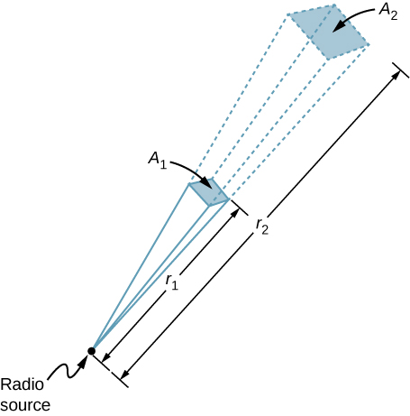
A point is labeled radio source. A small square labeled A1 is in the path of the lines radiating from the radio source. The lines continue from the corners of A1 and reach A2, a slightly bigger square. A1 is at a distance r1 from the source and A2 is at a distance R2. Figure 13.3.3 In three dimensions, a signal spreads over a solid angle as it travels outward from its source.
Strategy The area over which the power in a particular direction is dispersed increases as distance squared, as illustrated in the figure. Change the power output P by a factor of (90/60) and change the area by the same factor to keep I== the same. Then use the proportion of area A in the diagram to distance squared to find the distance that produces the calculated change in area.
Solution Using the proportionality of the areas to the squares of the distances, and solving, we obtain from the diagram
\[\frac{r_2^2}{r_1^2}=\frac{A_2}{A_1}=\frac{90~\mathrm{W}}{60~\mathrm{W}},\]
\[r_2=\sqrt{\frac{90}{60}}(100~\mathrm{km})=122~\mathrm{km}.\]
Significance The range of a radio signal is the maximum distance between the transmitter and receiver that allows for normal operation. In the absence of complications such as reflections from obstacles, the intensity follows an inverse square law, and doubling the range would require multiplying the power by four.
13.5 Radiation Pressure, Polarization
An electromagnetic wave incident on the object exerts forces on the charged particles, in accordance with the Lorentz force, Eq. 8-1. These forces do work on the particles of the object, increasing its energy. The energy that sunlight transports to us our body that we can very much feel in a tropical region of the world. However, most of the man made electromagnetic waves such as radio, telecom, TV electromagnetic signals are also exerting radiation pressure on us but that may not be felt by our skin due to its wavelength range fall outside the heat wave that sun rays fall. The electromagnetic radiation produces by exerting a force in the direction of the wave.
When the electric field is in the direction of the positive y-axis, electrons move in the negative y-direction, with the magnetic field in the direction of the positive z-axis. By applying the right-hand rule, and accounting for the negative charge of the electron, we can see that the force on the electron from the magnetic field is in the direction of the positive x-axis, which is the direction of wave propagation. When the E field reverses, the B field does too, and the force is again in the same direction. Maxwell’s equations together with the Lorentz force equation imply the existence of radiation pressure much more generally than this specific example, however.
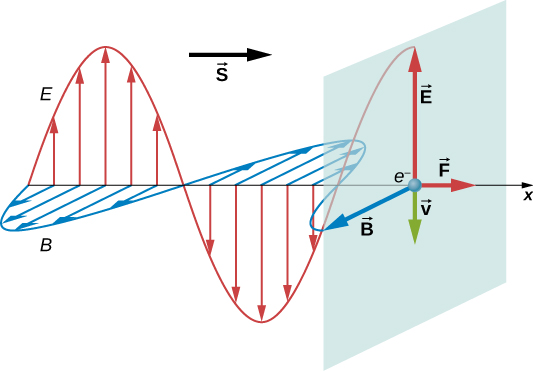
An electromagnetic wave propagates in the positive x direction. Its electric field is shown as a sine wave in the xy plane and magnetic field is shown as a sine wave in the xz plane. A vector \(\vec S\) points in the direction of propagation is called Poynting vector. Maxwell predicted that an electromagnetic wave carries momentum. An object absorbing an electromagnetic wave would experience a force in the direction of propagation of the wave. The force corresponds to radiation pressure exerted on the object by the wave. The force would be twice as great if the radiation were reflected rather than absorbed.
Maxwell’s prediction was confirmed in 1903 by Nichols and Hull by precisely measuring radiation pressures with a torsion balance. The schematic arrangement is shown in Figure 13.4.2. The mirrors suspended from a fibre were housed inside a glass container. Nichols and Hull were able to obtain a small measurable deflection of the mirrors from shining light on one of them. From the measured deflection, they could calculate the unbalanced force on the mirror, and obtained agreement with the predicted value of the force.
The force that exerts by the electromagnetic radiation can be expressed by Newton’s second law in terms of linear momentum, that a change in momentum is related to a force by
\[\begin{equation} F = \frac{\Delta p}{\Delta t} \tag{13.10} \end{equation}\]
We can express the force in terms of intensity I, which is defined to be
\[I = \frac {power}{area}=\frac {energy/time}{area}=\frac {\Delta U/\Delta t}{A}\] Assuming a flat surface of area A, perpendicular to the path of the radiation, intercepts the radiation. In time \(\Delta t\), the energy intercepted by area A is
\[\begin{equation} \Delta U = IA{\Delta t} \tag{13.11} \end{equation}\]
Maxwell showed that the object also gains linear momentum can also be related to the energy change \(\Delta U\) by
\[\begin{equation} \Delta p = \frac{\Delta U}{c}= \frac{IA{\Delta t}}{c} \tag{13.12} \end{equation}\]
If the energy is completely absorbed, then by substituting Eq. 13-4 in Eq. 13-2, we get the magnitude of the force on the area A is
\[\begin{equation} F = \frac{IA}{c}~~~~(total~absorption). \tag{13.13} \end{equation}\]
In case of the radiation that gets totally reflected back along its original path, Eq. 13-4 is multiplied by a factor of 2,
\[\begin{equation} \Delta p = \frac{2IA{\Delta t}}{c} \tag{13.14} \end{equation}\]
So, if the energy gets completely reflected, then by substituting Eq. 13-5 in Eq. 13-2, we get the magnitude of the force on the area A is
\[\begin{equation} F = \frac{2IA}{c}~~~~(total~reflection). \tag{13.15} \end{equation}\]
EXAMPLE 13.5.1: On February 9, 1986, Comet Halley was at its closest point to the Sun, about \(9.0\times10^{10}~\mathrm{m}\) from the centre of the Sun. The average power output of the Sun is \(3.8\times10^{26}~\mathrm{W}\).
Calculate the radiation pressure on the comet at this point in its orbit. Assume that the comet reflects all the incident light.
Suppose that a 10-kg chunk of material of cross-sectional area \(4.0\times10^{-2}~\mathrm{m}^2\) breaks loose from the comet. Calculate the force on this chunk due to the solar radiation. Compare this force with the gravitational force of the Sun.
Solution: Calculate the intensity of solar radiation at the given distance from the Sun and use that to calculate the radiation pressure. From the pressure and area, calculate the force.
a.The intensity of the solar radiation is the average solar power per unit area. Hence, at \(9.0\times10^{10}~\mathrm{m}\) from the center of the Sun, we have
\[I=S_{\mathrm{avg}}\frac{3.8\times10^{26}~\mathrm{W}}{4\pi(9.0\times10^{10}~\mathrm{m})^2}=3.7\times10^3~\mathrm{W/m}^2.\]
Assuming the comet reflects all the incident radiation, we obtain from Equation 13.4.3
\[p=\frac{2I}{c}=\frac{2(3.7\times10^3~\mathrm{W/m}^2)}{3.00\times10^8~\mathrm{m/s}}=2.5\times10^{-5}~\mathrm{N/m}^2.\]
- The force on the chunk due to the radiation is
\[F=pA=(2.5\times10^{-5}~\mathrm{N/m}^2)(4.0\times10^{-2}~\mathrm{m}^2)=1.0\times10^{-6}~\mathrm{N},\]
whereas the gravitational force of the Sun is
\[F_g=\frac{GMm}{r^2}=\frac{(6.67\times10^{-11}~\mathrm{N}\cdot\mathrm{m}^2.\mathrm{kg}^2)(2.0\times10^{30}~\mathrm{kg})(10~\mathrm{kg})}{(9.0\times10^{10}~\mathrm{m})^2}=0.16~\mathrm{N}.\]
Significance The gravitational force of the Sun on the chunk is therefore much greater than the force of the radiation.
After Maxwell showed that light carried momentum as well as energy, a novel idea eventually emerged, initially only as science fiction. Perhaps a spacecraft with a large reflecting light sail could use radiation pressure for propulsion. Such a vehicle would not have to carry fuel. It would experience a constant but small force from solar radiation, instead of the short bursts from rocket propulsion. It would accelerate slowly, but by being accelerated continuously, it would eventually reach great speeds. A spacecraft with small total mass and a sail with a large area would be necessary to obtain a usable acceleration.
When the space program began in the 1960s, the idea started to receive serious attention from NASA. The most recent development in light propelled spacecraft has come from a citizen-funded group, the Planetary Society. It is currently testing the use of light sails to propel a small vehicle built from CubeSats, tiny satellites that NASA places in orbit for various research projects during space launches intended mainly for other purposes.
The LightSail spacecraft shown below (Figure 13.4.4) consists of three CubeSats bundled together. It has a total mass of only about 5~ and is about the size as a loaf of bread. Its sails are made of very thin Mylar and open after launch to have a surface area of 32~^2.
(Figure 13.4.4) \[\begin{gather*}.\end{gather*}\]
Photograph showing two artificial satellites. Figure 13.4.4 Two small CubeSat satellites deployed from the International Space Station in May, 2016. The solar sails open out when the CubeSats are far enough away from the Station. INTERACTIVE The first LightSail spacecraft was launched in 2015 to test the sail deployment system. It was placed in low-earth orbit in 2015 by hitching a ride on an Atlas 5 rocket launched for an unrelated mission. The test was successful, but the low-earth orbit allowed too much drag on the spacecraft to accelerate it by sunlight. Eventually, it burned in the atmosphere, as expected. The Planetary Society’s LightSail 2 solar sailing spacecraft will launch aboard a SpaceX Falcon Heavy as soon as spring 2018, and will attempt the first controlled solar sail flight in Earth orbit. The following animation details the piece-by-piece construction of the LightSail 2 spacecraft as well as its maneuvers in space.
EXAMPLE 13.5.2: The intensity of energy from sunlight at a distance of \(1~\mathrm{AU}\) from the Sun is \(1370~\mathrm{W/m}^2\). The LightSail spacecraft has sails with total area of \(32~\mathrm{m}^2\) and a total mass of \(5.0~\mathrm{kg}\). Calculate the maximum acceleration LightSail spacecraft could achieve from radiation pressure when it is about \(1~\mathrm{AU}\) from the Sun.
Solution: The maximum acceleration can be expected when the sail is opened directly facing the Sun. Use the light intensity to calculate the radiation pressure and from it, the force on the sails. Then use Newton’s second law to calculate the acceleration.
The radiation pressure is
\[F=pA=2uA=\frac{2I}{c}A=\frac{2(1370~\mathrm{W/m}^2)(32~\mathrm{m}^2)}{(3.00\times10^8~\mathrm{m/s})}=2.92\times10^{-4}~\mathrm{N}.\]
The resulting acceleration is
\[a=\frac{F}{m}=\frac{2.92\times10^{-4}~\mathrm{N}}{5.0~\mathrm{kg}}=5.8\times10^{-5}~\mathrm{m/s}^2.\]
Significance If this small acceleration continued for a year, the craft would attain a speed of \(1829~\mathrm{m/s}\), or \(6600~\mathrm{km/h}\).
Solved Problems Electromagnetic Waves
[1] A certain helium–neon laser emits red light in a narrow band of wavelengths centered at 632.8 nm and with a “wavelength width” (such as on the scale of Fig. 33-1) of 0.0100 nm.What is the corresponding “frequency width” for the emission?
[6] What is the wavelength of the electromagnetic wave emitted by the oscillator–antenna system of Fig. 33-3 if L = 0.253 mH and C = 25.0 pF?
[10] A plane electromagnetic wave has a maximum electric field magnitude of \(3.20 \times 10^{-4}\) V/m. Find the magnetic field amplitude.
[13] Sunlight just outside Earth’s atmosphere has an intensity of 1.40 kW/\(m^2\). Calculate (a) \(E_m\) and (b) \(B_m\) for sunlight there, assuming it to be a plane wave.
[21] What is the radiation pressure 1.5 m away from a 500 W lightbulb? Assume that the surface on which the pressure is exerted faces the bulb and is perfectly absorbing and that the bulb radiates uniformly in all directions.
[26] In Fig. 33-38, a laser beam of power 4.60 W and diameter D = 2.60 mm is directed upward at one circular face (of diameter \(d \lt 2.60\) mm) of a perfectly reflecting cylinder. The cylinder is levitated because the upward radiation force matches the downward gravitational force. If the cylinder’s density is 1.20 g/cm3, what is its height H?
[35] In Fig. 33-41, a beam of light, with intensity 43 \(W/m^2\) and polarization parallel to a y axis, is sent into a system of two polarizing sheets with polarizing directions at angles of and u2 90” to the y axis.What is the intensity of the light transmitted by the two-sheet system?
[40] In Fig. 33-42, unpolarized light is sent into a system of three polarizing sheets. The angles \(\theta_1\), \(\theta_2\), and \(\theta_3\) of the polarizing directions are measured counterclockwise from the positive direction of the y axis (they are not drawn to scale). Angles \(\theta_1\) and \(\theta_3\) are fixed, but angle \(\theta_2\) can be varied. Figure 33-44 gives the intensity of the light emerging from sheet 3 as a function of \(\theta_2\). (The scale of the intensity axis is not indicated.) What percentage of the light’s initial intensity is transmitted by the three-sheet system when \(\theta_2 = 90^\circ\)?
[48] In Fig. 33-48a, a light ray in water is incident at angle \(\theta_1\) on a boundary with an underlying material, into which some of the light refracts. There are two choices of underlying material. For each, the angle of refraction \(\theta_2\) versus the incident angle \(\theta_1\) is given in Fig. 33-48b. The vertical axis scale is set by \(\theta_{2s} = 90^\circ\). Without calculation, determine whether the index of refraction of (a) material 1 and (b) material 2 is greater or less than the index of water (n = 1.33).What is the index of refraction of (c) material 1 and (d) material 2?
[52] In Fig. 33-52a, a beam of light in material 1 is incident on a boundary at an angle of \(\theta_1 = 30^\circ\).The extent of refraction of the light into material 2 depends, in part, on the index of refraction \(n_2\) of material 2. Figure 33-52b gives the angle of refraction \(\theta_2\) versus \(n_2\) for a range of possible \(n_2\) values. The vertical axis scale is set by \(\theta_{2a} = 20^\circ\) and \(\theta_{2b} = 40^\circ\). (a) What is the index of refraction of material 1? (b) If the incident angle is changed to \(60^\circ\) and material 2 has \(n_2\) = 2.4, then what is angle \(\theta_2\)?
[56] Rainbows from square drops. Suppose that, on some surreal world, raindrops had a square cross section and always fell with one face horizontal. Figure 33-56 shows such a falling drop, with a white beam of sunlight incident at \(\theta = 70.0^\circ\) at point P. The part of the light that enters the drop then travels to point A, where some of it refracts out into the air and the rest reflects. That reflected light then travels to point B, where again some of the light refracts out into the air and the rest reflects.What is the difference in the angles of the red light (n = 1.331) and the blue light (n = 1.343) that emerge at SSM (a) point A and (b) point B? (This angular difference in the light emerging at, say, point A would be the rainbow’s angular width.)
[60] In Fig. 33-58, light from ray A refracts from material 1 (\(n_1 = 1.60\)) into a thin layer of material 2 (\(n_2 = 1.80\)), crosses that layer, and is then incident at the critical angle on the interface between materials 2 and 3 (\(n_3 = 1.30\)). (a) What is the value of incident angle \(\theta_A\)? (b) If \(\theta_A\) is decreased, does part of the light refract into material 3? Light from ray B refracts from material 1 into the thin layer, crosses that layer, and is then incident at the critical angle on the interface between materials 2 and 3. (c) What is the value of incident angle \(\theta_B\)? (d) If \(\theta_B\) is decreased, does part of the light refract into material 3?
[64] Suppose the prism of Fig. 33-53 has apex angle \(\phi = 60.0^\circ\) and index of refraction n = 1.60. (a) What is the smallest angle of incidence \(\theta\) for which a ray can enter the left face of the prism and exit the right face? (b) What angle of incidence \(\theta\) is required for the ray to exit the prism with an identical angle \(\theta\) for its refraction, as it does in Fig. 33-53?
[70] In Fig. 33-64, a light ray in air is incident on a flat layer of material 2 that has an index of refraction \(n_2\) = 1.5. Beneath material 2 is material 3 with an index of refraction \(n_3\). The ray is incident on the air–material 2 interface at the Brewster angle for that interface.The ray of light refracted into material 3 happens to be incident on the material 2 – material 3 interface at the Brewster angle for that interface.What is the value of \(n_3\)?
Problems Electromagnetic Waves
Section 13-1 Electromagnetic Waves
- [4] About how far apart must you hold your hands for them to be separated by 1.0 nano-light-second (the distance light travels in 1.0 ns)?
Section 13-2 Energy Transport and the Poynting Vector
[8] Assume (unrealistically) that a TV station acts as a point source broadcasting isotropically at 1.0 MW. What is the intensity of the transmitted signal reaching Proxima Centauri, the star nearest our solar system, 4.3 ly away? (An alien civilization at that distance might be able to watch X Files.) A light-year (ly) is the distance light travels in one year.
[11] A plane electromagnetic wave traveling in the positive direction of an x axis in vacuum has components \(E_x = E_y = 0\) and \(E_z = (2.0 V/m) \cos[(\pi ( 10^{15} s^{-1})(t - x/c)]\). (a) What is the amplitude of the magnetic field component? (b) Parallel to which axis does the magnetic field oscillate? (c) When the electric field component is in the positive direction of the z axis at a certain point P, what is the direction of the magnetic field component there?
[15] An airplane flying at a distance of 10 km from a radio transmitter receives a signal of intensity 10 mW/m2. What is the amplitude of the (a) electric and (b) magnetic component of the signal at the airplane? (c) If the transmitter radiates uniformly over a hemisphere, what is the transmission power?
Section 13-3 Radiation Pressure
[19] High-power lasers are used to compress a plasma (a gas of charged particles) by radiation pressure. A laser generating radiation pulses with peak power 1.5 ( 103 MW is focused onto 1.0 mm2 of high-electron-density plasma. Find the pressure exerted on the plasma if the plasma reflects all the light beams directly back along their paths.
[24] It has been proposed that a spaceship might be propelled in the solar system by radiation pressure, using a large sail made of foil. How large must the surface area of the sail be if the radiation force is to be equal in magnitude to the Sun’s gravitational attraction? Assume that the mass of the ship ’ sail is 1500 kg, that the sail is perfectly reflecting, and that the sail is oriented perpendicular to the Sun’s rays. See Appendix C for needed data. (With a larger sail, the ship is continuously driven away from the Sun.)
Section 13-4 Polarization
[32] In Fig. 33-40, initially unpolarized light is sent into a system of three polarizing sheets whose polarizing directions make angles of \(\theta_1 = \theta_2 = \theta_3 = 50^\circ\) with the direction of the y axis. What percentage of the initial intensity is transmitted by the system? (Hint: Be careful with the angles.)
[38] In Fig. 33-42, unpolarized light is sent into a system of three polarizing sheets. The angles \(\theta_1\), \(\theta_2\), and \(\theta_3\) of the polarizing directions are measured counterclockwise from the positive direction of the y axis (they are not drawn to scale). Angles \(\theta_1\) and \(\theta_3\) are fixed, but angle \(\theta_2\) can be varied. Figure 33-43 gives the intensity of the light emerging from sheet 3 as a function of \(\theta_2\). (The scale of the intensity axis is not indicated.) What percentage of the light’s initial intensity is transmitted by the system when \(\theta = 30^\circ\)?
Section 13-5 Reflection and Refraction
[45] When the rectangular metal tank in Fig. 33-46 is filled to the top with an unknown liquid, observer O, with eyes level with the top of the tank, can just see corner E. A ray that refracts toward O at the top surface of the liquid is shown. If D = 85.0 cm and L = 1.10 m, what is the index of refraction of the liquid?
[50] In Fig. 33-50a, a beam of light in material 1 is incident on a boundary at an angle \(\theta_1=40^\circ\). Some of the light travels through material 2, and then some of it emerges into material 3. The two boundaries between the three materials are parallel. The final direction of the beam depends, in part, on the index of refraction n3 of the third material. Figure 33-50b gives the angle of refraction u3 in that material versus \(n_3\) for a range of possible \(n_3\) values. The vertical axis scale is set by \(\theta_{3a} = 30^\circ\) and \(\theta_{3b} = 50^\circ\). (a) What is the index of refraction of material 1, or is the index impossible to calculate without more information? (b) What is the index of refraction of material 2, or is the index impossible to calculate without more information? (c) If \(\theta_1\) is changed to \(70^\circ\) and the index of refraction of material 3 is 2.4, what is \(\theta_3\)?
[54] Dispersion in a window pane. In Fig. 33-54, a beam of white light is incident at angle \(\theta = 50^\circ\) on a common window pane (shown in cross section). For the pane’s type of glass, the index of refraction for visible light ranges from 1.524 at the blue end of the spectrum to 1.509 at the red end. The two sides of the pane are parallel. What is the angular spread of the colors in the beam (a) when the light enters the pane and (b) when it emerges from the opposite side? (Hint: When you look at an object through a window pane, are the colors in the light from the object dispersed as shown in, say, Fig. 33-20?)
Section 13-6 Total Internal Reflection
[58] The index of refraction of benzene is 1.8. What is the critical angle for a light ray traveling in benzene toward a flat layer of air above the benzene?
[62] A catfish is 2.00 m below the surface of a smooth lake.
- What is the diameter of the circle on the surface through which the fish can see the world outside the water? (b) If the fish descends, does the diameter of the circle increase, decrease, or remain the same?
- [66] In Fig. 33-62, a light ray in air is incident at angle u1 on a block of transparent plastic with an index of refraction of 1.56. The dimensions indicated are H = 2.00 cm and W = 3.00 cm. The light passes through the block to one of its sides and there undergoes reflection (inside the block) and possibly refraction (out into the air). This is the point of first reflection. The reflected light then passes through the block to another of its sides—a point of second reflection. If \(\theta_1 = 40^\circ\), on which side is the point of (a) first reflection and (b) second reflection? If there is refraction at the point of (c) first reflection and (d) second reflection, give the angle of refraction; if not, answer “none.” If \(\theta_1 = 70^\circ\), on which side is the point of (e) first reflection and (f) second reflection? If there is refraction at the point of (g) first reflection and (h) second reflection, give the angle of refraction; if not, answer “none.”
Section 13-7 Polarization by Reflection
- [68] (a) At what angle of incidence will the light reflected from water be completely polarized? (b) Does this angle depend on the wavelength of the light?