Chapter 5 Capacitance
Learning Objectives:
In this chapter you will basically learn:
\(\bullet\) Learn what is a capacitor, charging of a capacitor, the techniques of calculating the capacitance.
\(\bullet\) Learn the parallel plate, cylindrical and spherical capacitors and an isolated capacitor.
\(\bullet\) Learn the capacitors in parallel and in series.
\(\bullet\) Learn the energy, and energy density in a capacitor. Also, learn the potential energy and energy density of an electric field in capactors.
\(\bullet\) Learn the effect of dielectric in a capacitor, dielectrics and Gauss’ law.
5.1 Capacitor:
A capacitor is an electrical device in which electrical energy can be stored in the form of electric fields. Capacitors have applications ranging from tuning radio frequencies to energy storage in heart defibrillators. A typical commercial capacitor has two conducting plates separated with a dielectric material in between the plates as shown in Figure 5-1.

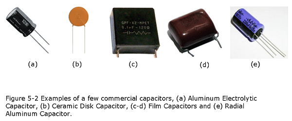
When battery terminals are connected to an initially uncharged capacitor, the battery potential moves a small amount of charge of magnitude Q from the positive plate to the negative plate. The capacitor remains neutral overall, but with charges +Q and -Q residing on opposite plates. Figure 5-2 shows pictures of some of the commercially used capacitors of various strengths, sizes and shapes.
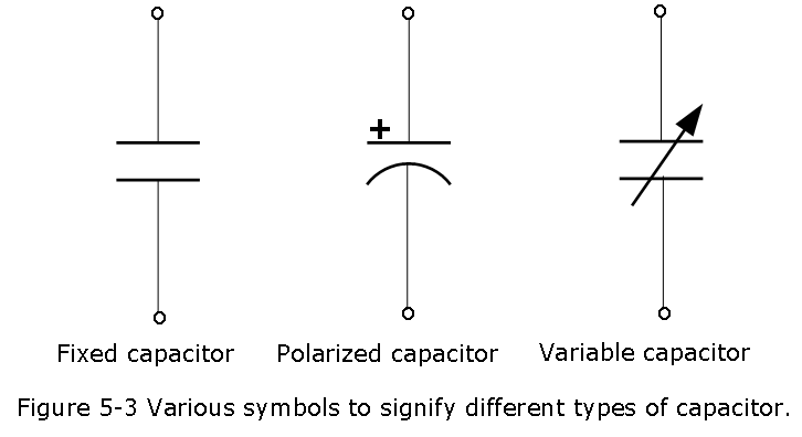
There are three commonly used capacitor symbols. One symbol represents a polarized (usually electrolytic or tantalum) capacitor, and the other is for non-polarized capacitor.
The symbol with one curved plate indicates that the capacitor is polarized. The curved plate usually represents the cathode of the capacitor, which should be at a lower voltage than the positive, anode pin. A plus sign should also be added to the positive pin of the polarized capacitor symbol as shown in Fig. 5-3.
5.2 Capacitance:
A capacitor consists of two isolated conductors or plates having various insulating materials in between the plates. Applying voltage V in the capacitors charges +q and -q build in the plates in accordance with the polarities of the battery or power source. The magnitude of charge \(|q|=|-q|=q\) in each plate increases as the applied voltage increases and the proportionality constant between q and V is called the capacitance C as defined by:
\[\begin{equation} q = CV \tag{5.1} \end{equation}\]
The SI unit of capacitance that follows from Eq. 5-1 is the coulomb per volt. This unit occurs so often that it is given a special name, the farad (F):
\[\begin{equation} 1~farad = 1~\mathrm F = 1~coulomb~per~volt = \frac{1~\mathrm C}{V} \tag{5.2} \end{equation}\]
Here C stands for Coulomb (C) on the right hand side of Eqn.5-2. Note that SI unit to represent capacitance is italicized \(\it C\).
5.3 Calculating the Capacitance in Parallel Plates Capacitor:
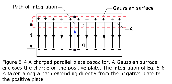
Capacitors are made in various geometries. The simplest capacitor is called parallel plate capacitors as shown in Figure 5-4, consisting of two parallel conducting plates of area A separated by a distance d. The symbol that represents a capacitor \(\left(-||-\right)\) signifies the structure of a parallel-plate capacitor but it is used for capacitors of all geometries. We assume for the time being that no material medium (such as glass or plastic) is present in the region between the plates.
The SI unit farad is a very large value of the capacitance. Frquently, used commercial capacitors are in the range of the microfarad \(1 \mu \mathrm F= 10^{-6}\space F\) and the picofarad
\(1 \space p\space F= 10^{-12}\space F\) convenient units in practice.
To find the capacitance for various capacitors with different geometries it is required to calculate the electric field between the plates of a capacitor to the charge q on either plate, using Gauss’ law:
\[\begin{equation} \varepsilon_0\oint {\vec E.d\vec A} = q ~~~~~~ (Gauss'~Law) \tag{5.3} \end{equation}\]
In all cases that we shall consider, the Gaussian surface will be such that whenever there is an electric flux through it, will have a uniform magnitude E and the vectors \(\vec E\) and \(d\vec E\)will be parallel. Equation 5-3 then reduces to
\[\begin{equation} \varepsilon_0{EA} = q ~~~~~~ (special~case~of~Eq.~5.3) \tag{5.4} \end{equation}\]
in Eq. 5-4, A is the area of that part of the Gaussian surface through which there is a flux that encloses the charge on the positive plate as shown in Fig. 5-4.
In Chapter 4 (Eq. 4-11), the potential difference between the plates of a capacitor is related to the field by
\[\begin{equation} V_f-V_i = -\int_{i}^{f} \vec E.d\vec s \tag{5.5} \end{equation}\]
in which the integral is to be evaluated from the negative plate to the positive plate. For this path, the vectors \(\vec E\) and \(d\vec s\) will have opposite directions; so the dot product \(\vec E. d\vec s\) will be equal to \(-Eds\).Thus, the right side of Eq. 5-5 will then be positive. Letting V represent the difference \(V_f - V_i\), we can then rewrite Eq. 5-5 as
\[\begin{equation} V = \int_{-}^{+} Eds ~~~~~~(special~case~of~Eq.5.5) \tag{5.6} \end{equation}\]
The limits of integration in Equation 5-6 yields
\[\begin{equation} V = E\int_{0}^{d} ds = Ed \tag{5.7} \end{equation}\]
Now using \(q = \varepsilon_0 EA\) and \(q = CV\), we can find the expression for capacitance for parallel plates as follows:
\[\begin{equation} \it C = \frac{\varepsilon_0A}{d} \tag{5.8} \end{equation}\]
In Eq. 5-8 we see that capacitance depends only on geometrical factors—namely, the plate area A and the plate separation d. The capacitance C increases as we increase area A or decrease separation d. Also, since we assumed vacuum in between the parallel plates, the permittivity constant \(\varepsilon_0\) is taken into consideration and its value is given by
\[\varepsilon_0 = 8.85\times 10^{-12}~\mathrm F/m\] Previously, we express the permittivity constant \(\varepsilon_0\) in \[\epsilon_{0}= 8.85 \times 10^{-12}{\frac{\mathrm C^2}{\mathrm N.m^2}}\].
Example Problem 5.01
- What is the capacitance of an empty parallel-plate capacitor with metal plates that each have an area of \(1.00~m^2\), separated by $1.00~mm? (b) How much charge is stored in this capacitor if a voltage of 5.00^3~V is applied to it?
Solution:
- Plug in the given values into Eq. 5.8 gives
\[C=\frac{\varepsilon_0 A}{d} =\left(8.85\times10^{-12}~\frac{\mathrm F}{m}\right)\frac{1.00~\mathrm{m}^2}{1.00\times10^{-3}~\mathrm{m}}=8.85\times10^{-9}~\mathrm{F}=8.85~\mathrm{nF}~(Answer)\]
- Inserting values in \(C = \frac{q}{V}\)
\[q=CV=(8.85\times10^{-9}~F)(5.00\times10^3~V)=44.25~\mu C~(Answer)\] Example Problem 5.02
Construct a parallel-plate capacitor with a capacitance of 1.0~F. What area must you use for each plate if the plates are separated by 1.0~mm?
Solution:
\[A=\frac{Cd}{\varepsilon_0}=\frac{(1.0~F)(1.0\times10^{-3}~m)}{8.85\times10^{-12}~{F/m}}=1.1\times10^8~m^2~(Answer)\]
So, a parallel plate capacitor having \(1~F\) value would require a square plate with side of \(10~km\).
Example Problem 5.03
In Fig. 5-5a, switch S is closed to connect the uncharged capacitor of capacitance C = 0.25 \(\mu F\) to the battery of potential difference V = 12 V.The lower capacitor plate has thickness L = 0.50 cm and face area \(A = 2.0 \times 10^{-4} m^2\), and it consists of copper, in which the density of conduction electrons is \(n = 8.49 \times 10^{28}\space electrons/m^3\). From what depth d within the plate (Fig. 5-5b) must electrons move to the plate face as the capacitor becomes charged?
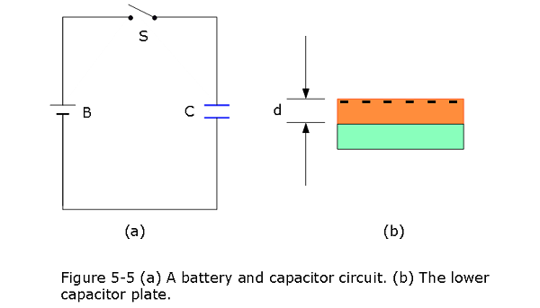
Solution:
The total charge magnitude \[q = CV = (0.25~ \mu F)(12~V)= 3~\mu C\]
Dividing total charge, q by e gives us the number N of conduction electrons that come up to the face:
\[N = \frac{q}{e} = \frac{3~\mu \mathrm C}{1.6\times 10^{-19}~\mathrm C}=1.873\times 10^{13}~electrons\] These electrons come from a volume that is the product of the face area A and the depth d we seek.Thus, from the density of conduction electrons (number per volume), we can write
\[d = \frac{N}{An}= \frac{(1.873\times 10^{13}~electrons)}{(2.0 \times 10^{-4} ~m^2)(8.49 \times 10^{28}\space electrons/m^3)}=1.1\times 10^{-12}~m=1.1~pm~(Answer)\]
5.4 Calculating the Capacitance in Cylindrical Capacitor:
Figure 5-6 shows, a cylindrical capacitor of length L formed by two coaxial cylinders of radii a and b. We assume that \(L \gg b\) so that we can neglect the fringing of the electric field that occurs at the ends of the cylinders. Each plate contains a charge of magnitude q.
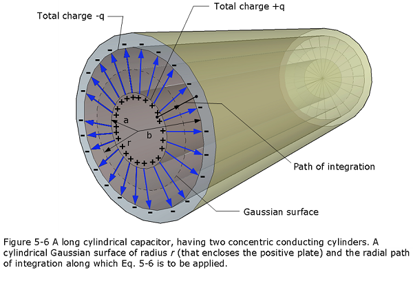
As a Gaussian surface, we choose a cylinder of length L and radius r, closed by end caps and placed as is shown in Fig. 25-6. It is coaxial with the cylinders and encloses the central cylinder and thus also the charge q on that cylinder. Equation 25-4 then relates that charge and the field magnitude E as
\[q=\varepsilon_0EA=\varepsilon_0E(2\pi rL)\] \[\begin{equation} E = \frac{q}{2\pi\varepsilon_0Lr} \tag{5.9} \end{equation}\]
Substitution of this result into Eq. 5-6 yields
\[\begin{equation} V = \int_{-}^{+} Eds = -\frac{q}{2\pi\varepsilon_0L}\int_{b}^{a}\frac{dr}{r}= \frac{q}{2\pi\varepsilon_0L}ln\frac{b}{a} \tag{5.10} \end{equation}\]
where we have used the fact that here ds!#dr (we integrated radially inward). From the relation C = q/V, we then have
\[\begin{equation} C = {2\pi\varepsilon_0}\frac{L}{ln(\frac{b}{a})}~~~(cylindrical~capacitor). \tag{5.11} \end{equation}\]
5.5 Spherical Capacitor:
Figure 5-7 shows the cross sectional view of a capacitor that consists of two concentric spherical shells, of radii a and b.
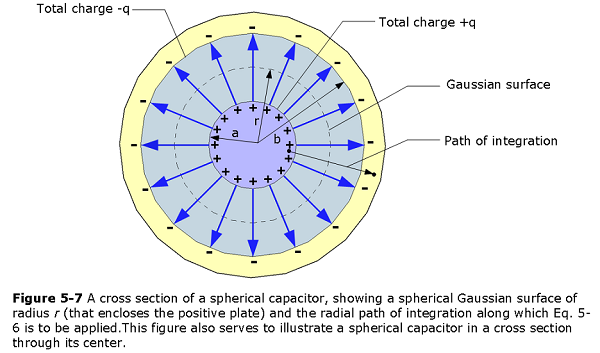
As a Gaussian surface we draw a sphere of radius r concentric with the two shells; then Eq. 5-4 yields
\[q=\varepsilon_0EA=\varepsilon_0E(4\pi r^2)\] in which \(4\pi r^2\) is the area of the spherical Gaussian surface. We solve this equation for E, obtaining
\[\begin{equation} E = \frac{1}{4\pi\varepsilon_{0}}\frac{q}{r^2} \tag{5.12} \end{equation}\]
If we substitute this expression into Eq. 5-6, we find
\[\begin{equation} V = \int_{-}^{+} Eds = -\frac{q}{4\pi\varepsilon_{0}}\int_{b}^{a}\frac{dr}{r^2}= \frac{q}{4\pi\varepsilon_{0}}\left(\frac{1}{b}-\frac{1}{a}\right)=\frac{q}{4\pi\varepsilon_{0}}\frac{b-a}{ab} \tag{5.13} \end{equation}\]
where again we have substituted -dr for ds. If we now substitute Eq. 5-13 into Eq. 5-1 and solve for C, we find
\[\begin{equation} C = 4\pi\varepsilon_{0}\frac{ab}{b-a}~~(spherical~capacitor). \tag{5.14} \end{equation}\]
5.6 An Isolated Sphere:
To find the capacitance of the conductor, we first rewrite Eq. 5-14 as \[C = 4\pi\varepsilon_{0}\frac{a}{1-a/b}\] If we then let \({b \to \infty}\) and substitute R for a, we find
\[\begin{equation} C = 4\pi\epsilon_{0}R~~(isolated~capacitor). \tag{5.15} \end{equation}\]
Note that Eq. 5-15, Eq. 5-14, Eq. 5-11, and Eq. 5-8 involve the constant \(\varepsilon_0\) multiplied by a quantity that has the dimensions of a length.
5.7 Capacitors in Parallel:
Figure 5-8a shows an electric circuit in which three capacitors are connected in parallel to battery B.
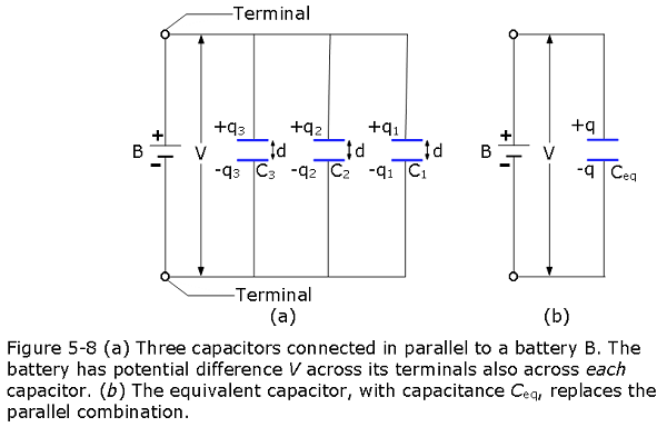
When a potential difference V is applied across several capacitors connected in parallel, that potential difference V is applied across each capacitor.The total charge q stored on the capacitors is the sum of the charges stored on all the capacitors.
To derive an expression for \(C_{eq}\) in Fig. 5-8b, we first use Eq. 5-1 to find the charge on each actual capacitor:
\[q_1 = C_1V,~~q_2 = C_2V,~~and~~q_3 = C_3V\] The total charge on the parallel combination of Fig. 5-8a is then
\[q = q_1 + q_2 + q_3 = (C_1 + C_2 + C_3)V.\] The equivalent capacitance, with the same total charge q and applied potential difference V as the combination, is then
The total capacitance of capacitors in parallel, C1,C2,C3:
\[\begin{equation} C_{eq} = \frac{q}{V} = C_1+C_2+C_3 \tag{5.16} \end{equation}\]
a result that we can easily extend to any number n of capacitors, as
\[\begin{equation} C_{eq} = \sum_{j=1}^{n} C_j ~~~(n~capacitors~ in~ parallel). \tag{5.17} \end{equation}\]
5.8 Capacitors in Series:
Figure 5-9a shows three capacitors connected in series to battery B.This description has little to do with how the capacitors are drawn. Rather,“in series” means that the capacitors are wired serially, one after the other, and that a potential difference V is applied across the two ends of the series. (In Fig. 25-9a, this potential difference V is maintained by battery B.) The potential differences that then exist across the capacitors in the series produce identical charges q on them.
When a potential difference V is applied across several capacitors connected in series, the capacitors have identical charge q.The sum of the potential differences across all the capacitors is equal to the applied potential difference V.
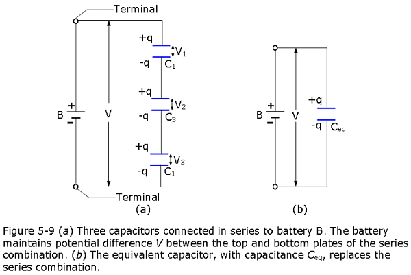
To derive an expression for \(C_{eq}\) in Fig. 5-9b, we first use Eq. 5-1 to find the potential difference of each actual capacitor:
\[V_1=\frac{q}{C_1},V_2=\frac{q}{C_2},~and~V_3=\frac{q}{C_3}\] The total potential difference V due to the battery is the sum: \[V=V_1+V_2+V_3=q\left(\frac{1}{C_1}+\frac{1}{C_2}+\frac{1}{C_3}\right)\]
The total capacitance of capacitors in series, \(C_1, C_2, C_3\): \[C_{eq}= \frac{q}{V}=\frac{1}{\frac{1}{C_{1}}+\frac{1}{C_{2}}+\frac{1}{C_{3}}}\]
\[\frac{1}{C_{eq}}= \frac{q}{V}=\frac{1}{C_{1}}+\frac{1}{C_{2}}+\frac{1}{C_{3}}\] \[\begin{equation} \frac{1}{C_{eq}} = \sum_{j=1}^{n} \frac{1}{C_j} ~~~(n~capacitors~ in~series). \tag{5.18} \end{equation}\]
Example Problem 5.04
Find the equivalent total capacitance for three capacitors connected in series, given their individual capacitances are \(1.000~\mu F\), \(5.000~\mu F\), and \(8.000~\mu F\).
Solution::
We enter the given capacitances into Eq. 5-18:
\[\begin{eqnarray} \frac{1}{C_{\mathrm{S}}}&=&\frac{1}{C_1}+\frac{1}{C_2}+\frac{1}{C_3}\\&=&\frac{1}{1.000~\mu\mathrm{F}}+\frac{1}{5.000~\mu\mathrm{F}}+\frac{1}{8.000~\mu\mathrm{F}}\\&=&\frac{1.325}{\mu\mathrm{F}}. \end{eqnarray}\]
Now we invert this result and obtain \[C_S=\frac{\mu F}{1.325}=0.755~\mu F~(Answer)\]
Example Problem 5.05
Find the net capacitance for three capacitors connected in parallel, given their individual capacitances are \(1.0~\mu F\), \(5.0~\mu F\), and \(8.0~\mu F\).
Solution:
Entering the given capacitances into Eq. 5-17 yields
\[\begin{eqnarray} C_P = C_1 + C_2 + C_3 = 1.0~\mu F+ 5.0~\mu F + 8.0~\mu F = 14.0~\mu F. \end{eqnarray}\]
Example Problem 5.06
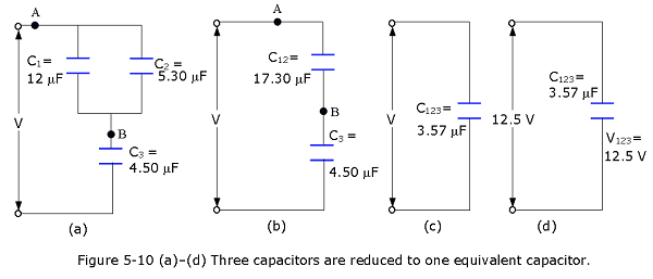
Capacitors in parallel and in series, (a) Find the equivalent capacitance for the combination of capacitances shown in Fig. 5-10a, across which potential difference V is applied. Assume \(C_1\) = 12.0 mF, \(C_2\) = 5.30 mF, and \(C_3\) = 4.50 mF. (b) The potential difference applied to the input terminals in Fig. 5-10a is V = 12.5 V.What is the charge on \(C_1\)?
Solution:
- \[C_{12} = C_1 + C_2 = 12.0 \mu F + 5.30 \mu F = 17.3 \mu F\]. \[\frac{1}{C_{123}}=\frac{1}{C_{12}}+\frac{1}{C_3}=\frac{1}{{17.3~\mu F}}+\frac{1}{4.5~\mu F}=0.280\space (\mu F)^{-1}\] \[C_{123}=\frac{1}{0.280\space (\mu F)^{-1}}=3.57~\mu F\space (Answer)\]
- \[q_{123} = C_{123}V = (3.57 ~\mu F)(12.5 ~V) = 44.6 ~\mu C\]
\[q_{12} = q_{123} = 44.6 \mu C\] $$V_{12} = =
= 2.58 ~V$$
\[V_1 = V_{12} = 2.58 ~V\]
\[q_1 = C_1V_1 = (12.0 ~\mu F)(2.58 ~V)= 31.0~\mu C\space (Answer)\]
5.9 Capacitor’s current
The capacitor’s momentary current \(i_c(t)\) is equal to the capacitance of the capacitor, times the derivative of the momentary capacitor’s voltage \(v_c(t)\):
\[\begin{equation} i_c(t)=C\frac{dv_c(t)}{dt} \tag{5.19} \end{equation}\]
5.10 Capacitor’s voltage
The capacitor’s momentary voltage \(v_c(t)\) is equal to the initial voltage of the capacitor, plus 1/C times the integral of the momentary capacitor’s current \(i_c(t)\) over time t:
\[\begin{equation} v_c(t)=v_c(0)+\frac{1}{C}\int_{0}^{t}i_c(\tau)d\tau \tag{5.20} \end{equation}\]
5.11 Energy Stored in an Electric Field:
Suppose that, at a given instant, a charge q’ has been transferred from one plate of a capacitor to the other. The potential difference V’ between the plates at that instant will be q’/C. If an extra increment of charge dq’ is then transferred, the increment of work required will be,
\[dW = V'dq' = \frac{q'}{C}dq'\] The work required to bring the total capacitor charge up to a final value q is
\[W = \int dW = \frac{1}{C}\int_0^q q'dq'= \frac{q^2}{2C}\]
The electric potential energy U of a charged capacitor,
\[\begin{equation} U_E = \frac{q^2}{2C}=\frac{1}{2}CV^2 \tag{5.21} \end{equation}\]
is equal to the work required to charge the capacitor. This energy can be associated with the capacitor’s electric field \(\vec E\). By extension we can associate stored energy with any electric field. In vacuum, the energy density u, or potential energy per unit volume,within an electric field of magnitude E is given by
\[\begin{equation} u_E = \frac{1}{2}\varepsilon_0E^2 ~~~(electric~energy~density). \tag{5.22} \end{equation}\]
Example Problem 5.07
An isolated conducting sphere whose radius R is 6.85 cm has a charge q = 1.25 nC. (a) How much potential energy is stored in the electric field of this charged conductor? (b) What is the energy density at the surface of the sphere?
Solution:
- An isolated sphere has capacitance given by Eq. 5-15 \((C = 4\pi \varepsilon_0R)\). (2) The energy U stored in a capacitor depends on the capacitor’s charge q and capacitance C according to Eq. 5-21 \((U = \frac{q^2}{2C}\).
\[U= \frac{q^2}{2C}=\frac{q^2}{8\pi\varepsilon_0R}=\frac{(1.25\times 10^{-9}~C)^2}{8\pi(8.85\times 10^{-12}~C^2/N.m^2)(0.0865~m)}=103\times10^{-9}~J=103~nJ \] (b) Electric field at the surface of the sphere, as given by Eq. 2-4:
\[E = \frac{1}{4\pi\varepsilon_0}\frac{q}{R^2}\] The energy density is then \[u_E = \frac{1}{2}\varepsilon_0E^2=\frac{q^2}{32\pi^2\varepsilon_0R^4}=\frac{(1.25\times 10^{-9}~C)^2}{32\pi^2(8.85\times 10^{-12}~C^2/N.m^2)(0.0865~m)^4}=25.4~\mu J/m^3~(Answer)\]
5.12 Capacitor with a Dielectric:
In the real capacitor the space between the plates of a capacitor is completely filled with a dielectric material, the capacitance C is increased by a factor \(\kappa\), called the dielectric constant, which is characteristic of the material. As a result of the insertion of dielectric material, all electrostatic equations containing \(\varepsilon_0\) must be modified by replacing \(\varepsilon_0\) with \(\kappa\varepsilon_0\).
The result of filling the space between the plates of a capacitor with a dielectric or an insulating material such as mineral oil or plastic, resulted the increased in capacitance by a factor of \(\kappa\), which Michael Faraday in 1837 called dielectric constant of the insulating material. Table 5-1 shows some dielectric materials and their dielectric constants.
Table 5-1 Some Properties of Dielectrics\(^a\).
| Material | Dielectric Constant \(\kappa\) | Dielectric Strengths (kV/mm) |
|---|---|---|
| Air(1 atm) | 1.00054 | 3 |
| Polystyrene | 2.6 | 24 |
| Paper | 3.5 | 16 |
| Silicon oil | 2.5 | 10 to 15 |
| Pyrex | 4.7 | 14 |
| Fused quartz | 3.78 | 8 |
| Silicon | 12 | - |
| Germanium | 16 | - |
| Mica | 6.0 | 118 |
| Water | 80 | - |
| Titanium dioxide | 86 to 173 | - |
| Strontium titanate | 310 | 8 |
| Barium titanate | 1,200 to 10,000 | - |
| Calcium copper titanate | > 250,000 | - |
5.13 Dielectrics: An Atomic View:
The effect of applying electric field in the dielectric material of the capacitor resulted in two possibilities, depending on the type of molecule:
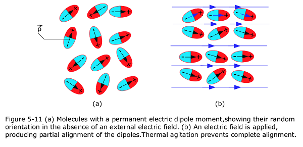
- Polar dielectrics. The molecules of some dielectrics, like water, have permanent electric dipole moments. Molecules with a permanent electric dipole moment, showing their random orientation in the absence of an external electric field as in Fig. 5-11a. In such materials (called polar dielectrics), the electric dipoles tend to line up with an external electric field as in Fig. 5-11b.
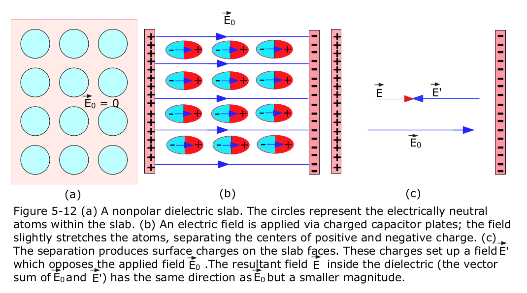
- Nonpolar dielectrics. Regardless of whether they have permanent electric dipole moments, molecules acquire dipole moments by induction when placed in an external electric field. In Fig. 5-12, we see that with the external field it tends to “stretch” the molecules, slightly separating the centers of negative and positive charge and thus create dipole moments in the microscopic scale.
5.14 Dielectrics and Gauss’ Law:
We already have an equation for electric field as given in Eq. 5-4, without a dielectric, as shown in Fig. 5-4. We enclosed the charge +q on the top plate with a Gaussian surface and then apply Gauss’ law as shown in Figure 5-13a.
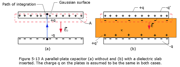
Letting \(E_0\) represent the magnitude of the field, we find
\[\begin{equation} \varepsilon_0\oint {\vec E.d\vec A} =\varepsilon_0EA = q \tag{5.23} \end{equation}\]
or
\[\begin{equation} \varepsilon_0EA = \frac{q}{\varepsilon_0A} \tag{5.24} \end{equation}\]
The insertion of a dielectric material in between the capacitor plates as shown in Figure 5-13b, Gauss’ law may be generalized to
\[\begin{equation} \varepsilon_0\oint {\kappa\vec E.d\vec A} = q \space\space (Gauss'~Law~with~Dielectric) \tag{5.25} \end{equation}\]
Here q is the free charge; any induced surface charge is accounted for by including the dielectric constant \(\kappa\) inside the integral.
With the insertion of dielectric material in between the plates will modify the Eqns. 5-8, 5-11, 5-15 as follows:
\[\begin{equation} C = \frac{\varepsilon_0\kappa A}{d}=\kappa C_{air}~~~(parallel~plate~capacitor~with~dielectric), \tag{5.26} \end{equation}\]
where \(C_{air}\) is the value of the capacitance with only air between the plates.
\[\begin{equation} C = {2\pi\varepsilon_0}\kappa\frac{L}{ln(\frac{b}{a})}~~~(cylindrical~capacitor~with~dielectric). \tag{5.27} \end{equation}\]
\[\begin{equation} C = 4\pi\varepsilon_0\kappa\frac{ab}{b-a}~~(spherical~capacitor~with~dielectric). \tag{5.28} \end{equation}\]
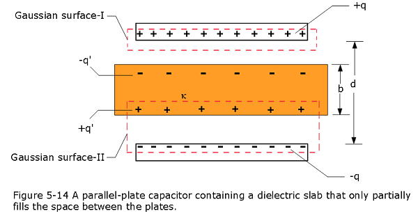
Example Problem 5.08
Figure 5-14 shows a parallel-plate capacitor of plate area A and plate separation d. A potential difference \(V_0\) is applied between the plates by connecting a battery between them. The battery is then disconnected, and a dielectric slab of thickness b and dielectric constant \(\kappa\) is placed between the plates as shown. Assume \(A = 115 cm^2\), d = 1.24 cm, \(V_0\) = 85.5 V, b = 0.780 cm, and \(\kappa\) = 2.61. (a) What is the capacitance C0 before the dielectric slab is inserted? (b) What free charge appears on the plates? (c) What is the electric field \(E_0\) in the gaps between the plates and the dielectric slab? (d) What is the electric field \(E_1\) in the dielectric slab? (e) What is the potential difference V between the plates after the slab has been introduced? (f) What is the capacitance with the slab in place?
Solution:
- \[C_0 = \frac{\varepsilon_0A}{d}=\frac{(8.85\times 10^{-12}~F/m)(115\times 10^{-4} ~m^2)}{1.24\times 10^{-2}~m}=8.21~pF~(Answer)\]
- \[q = C_0V_0= (8.21\times 10^{-12}~F)(85.5~ V)=702~pC~(Answer)\]
- That surface passes through the gap, and so it encloses only the free charge on the upper capacitor plate. Electric field pierces only the bottom of the Gaussian surface. Because there the area vector and the field vector are both directed downward, the dot product in Eq. 5-25 becomes
\[\varepsilon_0\oint {\kappa\vec E.d\vec A} = q \space\space\] \[\varepsilon_0\oint {\kappa E_0\cos0^\circ}dA = q\] \[E_0=\frac{q}{\varepsilon_0\kappa A}=\frac{702\times10^{-12}~C}{(8.85\times 10^{-12}~F/m)(1) (115\times 10^{-4} ~m^2)}=6.90~kV/m~(Answer)\] (d) Now we apply Gauss’ law in the form of Eq. 5-25 to Gaussian surface II in Fig. 5-14.
Only the free charge -q is in Eq. 5-25, so \[\varepsilon_0\oint {\kappa E_1\cos180^\circ}dA = -q\] \[E_0=\frac{q}{\varepsilon_0\kappa A}=\frac{702\times10^{-12}~C}{(8.85\times 10^{-12}~F/m)(2.61) (115\times 10^{-4} ~m^2)}=2.64~kV/m~(Answer)\] (e) Within the dielectric, the path length is b and the electric field is \(E_1\). Within the two gaps above and below the dielectric, the total path length is d - b and the electric field is \(E_0\). Equation 5-6 then yields
\[V = \int_{-}^{+} Eds=E_0(d-b)+E_1b\] \[V = (6900~V/m)(1.24\times 10^{-2}~m-0.78\times 10^{-2}~m)+(2640~V/m)(0.78\times 10^{-2}~m)=52.3~V~(Answer)\] (f) \[C = \frac{q}{V}=\frac{702\times10^{-12}~C}{52.3~V}=13.4~pF~(Answer)\]
Solved Problems Capacitance
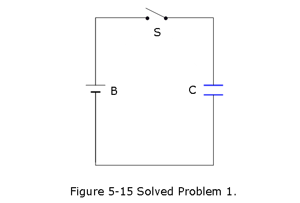
- [2] The capacitor in Fig. 5-15 has a capacitance of 25 \(\mu F\) and is initially uncharged. The battery provides a potential difference of 120 V. After switch S is closed, how much charge will pass through it?
Solution:
\[q = CV = (25~\mu~F)(120~V)=3.0\times 10^{-3}~C~(Answer)\]
- [3] A parallel-plate capacitor has circular plates of 8.20 cm radius and 1.30 mm separation. (a) Calculate the capacitance. (b) Find the charge for a potential difference of 120 V.
Solution:
- \[C = \frac{\varepsilon_0 A}{d}=\frac{\varepsilon_0 \pi r^2}{d}=\left(8.85\times10^{-12}~\frac{F}{m}\right)\frac{\pi\times (8.20\times 10^{-2}~{m})^2}{1.30\times10^{-3}~\mathrm{m}}=1.44\times 10^{-10}~F~(Answer)\]
- \[q =CV = (1.44\times 10^{-10}~F)(120~V)=1.73\times 10^{-8}~C~(Answer)\]
- [6] You have two flat metal plates, each of area 1.00 \(m^2\), with which to construct a parallel-plate capacitor. (a) If the capacitance of the device is to be 1.00 F, what must be the separation between the plates? (b) Could this capacitor actually be constructed?
Solution:
\[d = \frac{\varepsilon_0 A}{C} =\left(8.85\times10^{-12}~\frac{F}{m}\right)\frac{(1.0~{m^2})}{1.0~F}=8.85\times 10^{-12}~m~(Answer)\] (b) The separation,d is much smaller than the dimension of an atom (\(10^{-10}~m\)) and is not possible to build in the laboratory.
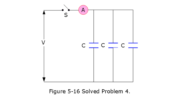
- [9] Each of the uncharged capacitors in Fig. 5-16 has a capacitance of 25.0 \(\mu F\). A potential difference of V = 4200 V is established when the switch is closed. How many coulombs of charge then pass through meter A?
Solution:
\[q = C_{eq}V = 3CV = 3(25.0\times10^{-6}~F)(4200~V)= 31.50\times 10^{-2}~C~(Answer)\]
- [11] In Fig. 5-17, find the equivalent capacitance of the combination. Assume that \(C_1 = 10.0 \mu F\), \(C_2 = 5.00 \mu F\), and \(C_3 = 4.00 \mu F\).
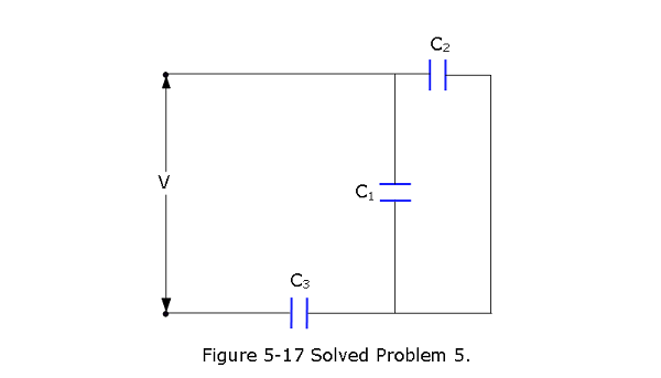
Solution:
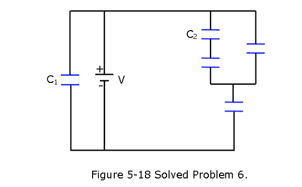
\[\frac{1}{C_{eq}}=\frac{1}{C_{3}}+\frac{1}{C_{1}+C_{2}}=\frac{(C_1+C_2)+C_3}{C_3(C_1+C_2)}\] \[C_{eq}=\frac{C_3(C_1+C_2)}{(C_1+C_2)+C_3}=\frac{4~\mu F(10~\mu F+5~\mu F)}{(10~\mu F+5~\mu F)+4~\mu F}=3.16~\mu F~(Answer)\] 6. [14] In Fig. 5-18, the battery has a potential difference of V = 10.0 V and the five capacitors each have a capacitance of 10.0 \(\mu F\). What is the charge on (a) capacitor 1 and (b) capacitor 2?
Solution:
Charge on capacitor 1, \[q_1 = C_1V = (10\times 10^{-6}~F)(10.0~V)=100~\mu C~(Answer)\]
\[\frac{1}{C_{eq1}}=\frac{1}{C_2}+\frac{1}{C}=\frac{C+C_2}{C_2C}\] \[C_{eq1}=\frac{C_2C}{C+C_2}\] Equivalent capacitance of the three capacitors on the right branch is \[C_{eq2} = C_{eq1}+C= C+\frac{C_2C}{C+C_2}=10~\mu F+\frac{(10~\mu F)(10~\mu F)}{10~\mu F+10~\mu F}=15~\mu F\] Total equivalent capacitance on the right branch is
\[C_{eq} = \frac{C_{eq2}C}{C+C_{eq2}}=\frac{(15~\mu F)(10~\mu F)}{10\mu F + 15~\mu F}=6~\mu F\] Total charge on the right branch is \(q = C_{eq}V = (6~\mu F)(10~V)= 60~\mu C\)
Voltage drop across the three capacitors on the right branch is
\[V' = \frac{q'}{C_{eq2}}=\frac{60\times 10~\mu C}{15~\mu F}=4.0~V\] Charge on the capacitor 2 is
\[q_2 = C_2V_2=C_2\frac{V'}{2}=(10~\mu F)\frac{4.0}{2}=20~\mu C~(Answer)\]
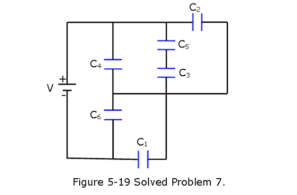
- [15] In Fig. 5-19, a 20.0 V battery is connected across capacitors of capacitances \(C_1 = C_6 = 3.00 \mu F\) and \(C_3 = C_5 = 2.00C_2 = 2.00C_4 = 4.00 \mu F\). What are (a) the equivalent capacitance \(C_{eq}\) of the capacitors and (b) the charge stored by \(C_{eq}\)? What are (c) \(V_1\) and (d) \(q_1\) of capacitor 1, (e) \(V_2\) and (f) \(q_2\) of capacitor 2, and (g) \(V_3\) and (h) \(q_3\) of capacitor 3?
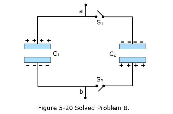
- [21] In Fig. 5-20, the capacitances are \(C_1 = 1.0 \mu F\) and \(C_2 = 3.0 \mu F\), and both capacitors are charged to a potential difference of V = 100 V but with opposite polarity as shown. Switches \(S_1\) and \(S_2\) are now closed. (a) What is now the potential difference between points a and b? What now is the charge on capacitor (b) 1 and (c) 2?
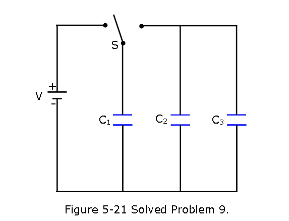
- [22] In Fig. 5-21,V = 10 V,\(C_1 = 10 \mu F\), and \(C_2 = C_3 = 20 \mu F\). Switch S is first thrown to the left side until capacitor 1 reaches equilibrium. Then the switch is thrown to the right. When equilibrium is again reached, how much charge is on capacitor 1?
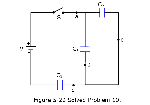
- [23] The capacitors in Fig. 5-22 are initially uncharged. The capacitances are \(C_1 = 4.0 \mu F\), \(C_2 = 8.0 \mu F\), and \(C_3 = 12 \mu F\), and the battery’s potential difference is V = 12 V. When switch S is closed, how many electrons travel through (a) point a, (b) point b, (c) point c, and (d) point d? In the figure, do the electrons travel up or down through (e) point b and (f) point c?
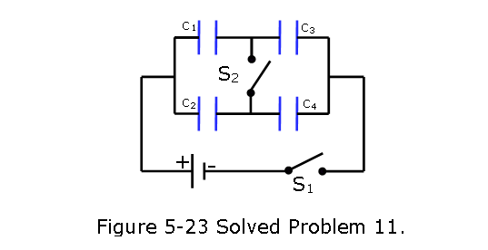
- [27] Figure 5-23 shows a 12.0 V battery and four uncharged capacitors of capacitances \(C_1 = 1.00 \mu F\), \(C_2 = 2.00 \mu F\),\(C_3 = 3.00 \mu F\), and \(C_4 = 4.00 \mu F\). If only switch S1 is closed, what is the charge on (a) capacitor 1, (b) capacitor 2, (c) capacitor 3, and (d) capacitor 4? If both switches are closed, what is the charge on (e) capacitor 1, (f) capacitor 2, (g) capacitor 3,and (h) capacitor 4?
[31] A \(2.0 \mu F\) capacitor and a \(4.0 \mu F\) capacitor are connected in parallel across a 300 V potential difference. Calculate the total energy stored in the capacitors.
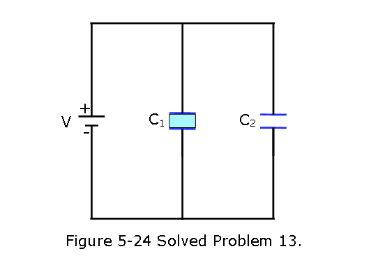
[46] In Fig. 5-24, how much charge is stored on the parallel-plate capacitors by the 12.0 V battery? One is filled with air, and the other is filled with a dielectric for which \(\kappa = 3.00\); both capacitors have a plate area of \(5.00 \times 10^{-3} m^2\) and a plate separation of 2.00 mm.
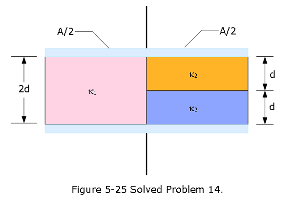
- [50] Figure 5-25 shows a parallel plate capacitor of plate area \(A = 10.5~cm^2\) and plate separation 2d = 7.12 mm. The left half of the gap is filled with material of dielectric constant \(\kappa_1 = 21.0\); the top of the right half is filled with material of dielectric constant \(\kappa_2 = 42.0\); the bottom of the right half is filled with material of dielectric constant \(\kappa_3 = 58.0\).What is the capacitance?
Problems Capacitance
Section 5-1 Capacitance
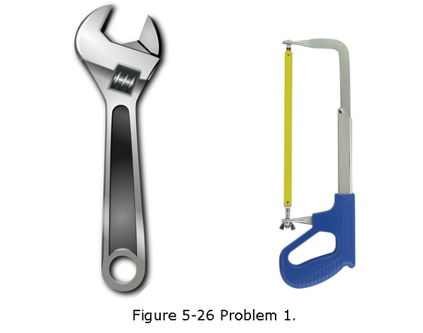
- [1] The two metal objects in Fig. 5-26 have net charges of +70 pC and -70 pC, which result in a 20 V potential difference between them. (a) What is the capacitance of the system? (b) If the charges are changed to +200 pC and -200 pC, what does the capacitance become? (c) What does the potential difference become?
Section 5-2 Calculating the Capacitance
[4] The plates of a spherical capacitor have radii 38.0 mm and 40.0 mm. (a) Calculate the capacitance. (b) What must be the plate area of a parallel-plate capacitor with the same plate separation and capacitance?
[5] What is the capacitance of a drop that results when two mercury spheres, each of radius R = 2.00 mm, merge?
Section 5-3 Capacitors in Parallel and in Series
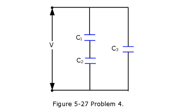
- [10] In Fig. 5-27, find the equivalent capacitance of the combination. Assume that \(C_1\) is \(10.0 \mu F\), \(C_2\) is \(5.00 \mu F\), and \(C_3\) is \(4.00 \mu F\).
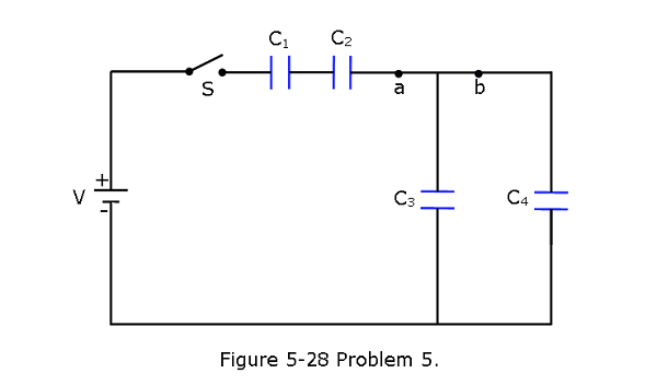
- [19] In Fig. 5-28, the battery has potential difference V = 9.0 V, \(C_2 = 3.0 \mu F\), \(C_4 = 4.0 \mu F\), and all the capacitors are initially uncharged. When switch S is closed, a total charge of \(12 \mu C\) passes through point a and a total charge of \(8.0 \mu C\) passes through point b. What are (a) \(C_1\) and (b) \(C_3\)?
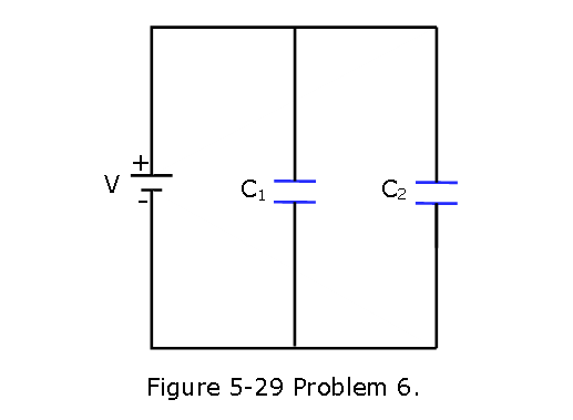
- [25] In Fig. 5-29, two parallel-plate capacitors (with air between the plates) are connected to a battery. Capacitor 1 has a plate area of 1.5 \(cm^2\) and an electric field (between its plates) of magnitude 2000 V/m. Capacitor 2 has a plate area of 0.70 \(cm^2\) and an electric field of magnitude 1500 V/m. What is the total charge on the two capacitors?
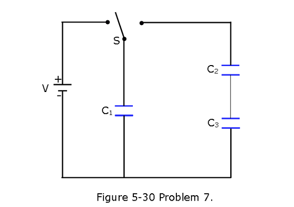
- [28] Figure 5-30 displays a 12.0 V battery and 3 uncharged capacitors of capacitances \(C_1 = 4.00 \mu F\), \(C_2 = 6.00 \mu F\), and \(C_3 = 3.00 \mu F\). The switch is thrown to the left side until capacitor 1 is fully charged. Then the switch is thrown to the right.What is the final charge on (a) capacitor 1, (b) capacitor 2, and (c) capacitor 3?
Section 5-3 Energy Stored in an Electric Field
[32] A parallel-plate air-filled capacitor having area 40 \(cm^2\) and plate spacing 1.0 mm is charged to a potential difference of 600 V. Find (a) the capacitance, (b) the magnitude of the charge on each plate, (c) the stored energy, (d) the electric field between the plates, and (e) the energy density between the plates.
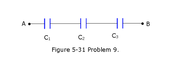
[39] In Fig. 5-31,\(C_1 = 10.0 \mu F\), \(C_2 = 20.0 \mu F\), and \(C_3 = 25.0 \mu F\). If no capacitor can withstand a potential difference of more than 100 V without failure, what are (a) the magnitude of the maximum potential difference that can exist between points A and B and (b) the maximum energy that can be stored in the three-capacitor arrangement?
Section 5-4 Capacitor with a Dielectric
[41] A coaxial cable used in a transmission line has an inner radius of 0.10 mm and an outer radius of 0.60 mm. Calculate the capacitance per meter for the cable. Assume that the space between the conductors is filled with polystyrene.
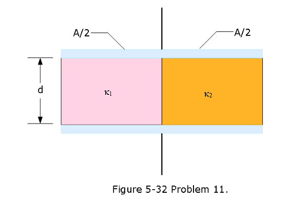
[48] Figure 5-32 shows a parallelplate capacitor with a plate area A = 5.56 \(cm^2\) and separation d = 5.56 mm. The left half of the gap is filled with material of dielectric constant \(\kappa_1 = 7.00\); the right half is filled with material of dielectric constant \(\kappa_2 = 12.0\). What is the capacitance?
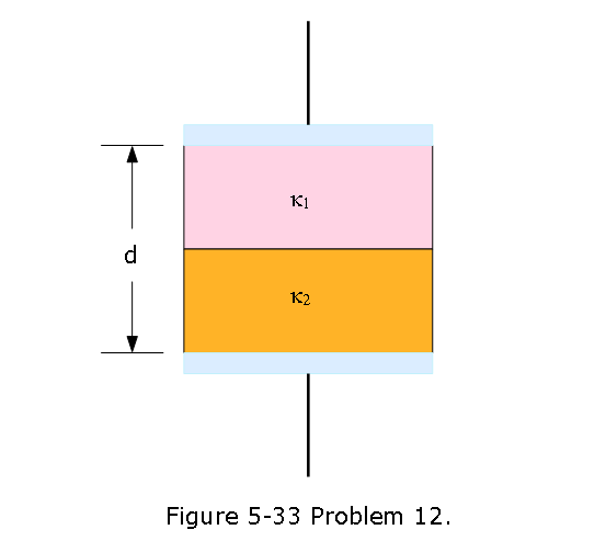
- [49] Figure 5-33 shows a parallel-plate capacitor with a plate area A = 7.89 \(cm^2\) and plate separation d = 4.62 mm. The top half of the gap is filled with material of dielectric constant \(\kappa_1 = 11.0\); the bottom half is filled with material of dielectric constant \(\kappa_2 = 12.0\). What is the capacitance?