Chapter 5 — Capacitors, Inductors, and DC Transients
Adapted from C. K. Alexander and M. N. O. Sadiku, Fundamentals of Electric Circuits.
Learning Objectives
After studying this chapter, you should be able to:
- Describe the voltage–current relationship of a capacitor and the energy it stores.
- Combine capacitors in series and parallel and apply voltage division to series capacitors.
- Describe the voltage–current relationship of an inductor and the energy it stores.
- Combine inductors in series and parallel and apply current division to parallel inductors.
- Determine initial and final (DC steady-state) conditions: a capacitor is an open circuit and an inductor is a short circuit at DC steady state.
- Derive and solve the differential equation of a first-order RC or RL circuit and interpret the time constant.
- Write and recognize the complete (natural + forced) response of first-order circuits.
- Analyze second-order series and parallel RLC circuits, including the overdamped, critically damped, and underdamped cases.
5.1 Introduction
So far we have studied circuits of resistors and sources, whose response is instantaneous. In this chapter we introduce the two energy-storage elements—the capacitor and the inductor. Because these elements store energy in electric and magnetic fields, their currents and voltages cannot change instantaneously (in general). When a source is switched on or off, the circuit goes through a transient period before reaching a new steady state. The objective of transient analysis is to describe the voltage or current during this transition.
We analyze first- and second-order circuits (circuits with one or two energy-storage elements, respectively). A general model is a network of resistors connected to a single energy-storage element, energized by a source switched at \(t = 0\).
5.2 Capacitors
A capacitor is a passive element that stores energy in an electric field. It consists of two conductors separated by an insulator (dielectric). The capacitance \(C\) (farads, F) relates the charge \(q\) on the plates to the voltage \(v\) across them:
\[ q = C v. \tag{5.1} \]
Taking the time derivative and using \(i = dq/dt\) gives the capacitor’s voltage–current relationship:
\[ \boxed{i = C\,\frac{dv}{dt}} \tag{5.2} \]
and, integrating, the voltage in terms of the current:
\[ v(t) = v(t_0) + \frac{1}{C}\int_{t_0}^{t} i(\tau)\, d\tau. \tag{5.3} \]
Key consequences: - The current through a capacitor is proportional to the rate of change of voltage. If \(v\) is constant (DC steady state), \(dv/dt = 0\) and \(i = 0\): a capacitor is an open circuit under DC steady state. - The voltage across a capacitor cannot change instantaneously (an abrupt \(\Delta v\) would require an infinite current). So \(v_C(0^+) = v_C(0^-)\).
The energy stored in a capacitor is
\[ \boxed{w = \tfrac{1}{2} C v^2} \tag{5.4} \]
in joules.
Example 5.1 (Example 6.1) — (a) Calculate the charge stored on a \(3\text{-pF}\) capacitor with \(20\) V across it. (b) Find the energy stored.
Solution:
\(q = Cv = (3\times10^{-12})(20) = 60\times10^{-12}\ \text{C} = 60\ \text{pC}.\)
\(w = \tfrac{1}{2} C v^2 = \tfrac{1}{2}(3\times10^{-12})(20)^2 = \tfrac{1}{2}(3\times10^{-12})(400) = 600\times10^{-12}\ \text{J} = 600\ \text{pJ}.\)
\[ \boxed{q = 60\ \text{pC},\quad w = 600\ \text{pJ}} \]
Practice Problem 5.1 (Practice Problem 6.1) — What is the voltage across a \(2\text{-}\mu\text{F}\) capacitor if the charge on one plate is \(0.12\) mC? How much energy is stored? [values reconstructed]
Solution:
\(v = q/C = (0.12\times10^{-3})/(2\times10^{-6}) = 60\ \text{V}.\)
\(w = \tfrac{1}{2} C v^2 = \tfrac{1}{2}(2\times10^{-6})(60)^2 = (10^{-6})(3600) = 3.6\times10^{-3}\ \text{J} = 3.6\ \text{mJ}.\)
\[ \boxed{v = 60\ \text{V},\quad w = 3.6\ \text{mJ}} \]
Example 5.2 (Example 6.3) — Determine the voltage across a capacitor if the current through it is \(i(t) = 6t\) A (for \(t \ge 0\)) and \(v(0) = 0\). [equation reconstructed]
Solution:
\[ v(t) = v(0) + \frac{1}{C}\int_0^t i(\tau)\,d\tau = 0 + \frac{1}{C}\int_0^t 6\tau\,d\tau = \frac{1}{C}\cdot 3t^2. \]
With (say) \(C = 2\) F: \(v(t) = 1.5\,t^2\) V. (Use the \(C\) from your figure.) [equation reconstructed]
\[ \boxed{v(t) = \frac{1}{C}\cdot 3t^2\ \text{V}} \]
Practice Problem 5.2 (Practice Problem 6.2) — If a \(10\text{-}\mu\text{F}\) capacitor is connected to a voltage source with \(v(t) = 50\,t\) V, determine the current through the capacitor. [values reconstructed]
Solution:
\[ i = C\,\frac{dv}{dt} = (10\times10^{-6})\frac{d}{dt}(50t) = (10^{-5})(50) = 500\ \mu\text{A}. \]
\[ \boxed{i = 500\ \mu\text{A}} \]
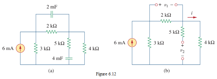
Example 5.3 (Example 6.5) — Obtain the energy stored in each capacitor in Fig. 6.12(a) under DC conditions. [values reconstructed: a bridge of resistors with two capacitors under DC]
Solution:
Under DC conditions, replace each capacitor with an open circuit (Fig. 6.12(b)). The current through the series combination of resistors is found by current division. The voltages \(v_1, v_2\) across the (now open) capacitors equal the node voltages; then
\[ w_1 = \tfrac{1}{2} C_1 v_1^2, \qquad w_2 = \tfrac{1}{2} C_2 v_2^2. \]
(Reproduce with the specific values in your figure.) [equation reconstructed]
5.3 Series and Parallel Capacitors
For \(N\) capacitors in parallel (same voltage), the equivalent capacitance is the sum:
\[ \boxed{C_{\text{eq}} = C_1 + C_2 + \cdots + C_N} \tag{5.5} \]
For \(N\) capacitors in series (same charge), the reciprocals add:
\[ \boxed{\frac{1}{C_{\text{eq}}} = \frac{1}{C_1} + \frac{1}{C_2} + \cdots + \frac{1}{C_N}} \tag{5.6} \]
(two capacitors: \(C_{\text{eq}} = C_1 C_2/(C_1+C_2)\)). Note this is the mirror image of resistors. For series capacitors, the voltage divider in terms of capacitance is
\[ v_1 = v\,\frac{C_2}{C_1 + C_2} \quad(\text{two series capacitors}), \]
i.e., the smaller capacitor takes the larger voltage. In general, for series capacitors, \(v_k = v\,(C_{\text{eq}}/C_k)\).
5.4 Inductors
An inductor is a passive element that stores energy in a magnetic field (a coil of wire). The inductance \(L\) (henries, H) is defined in terms of the magnetic flux linkage \(\lambda = N\Phi\) and the current:
\[ \lambda = L i, \qquad L = \frac{N\Phi}{i}. \]
By Faraday’s law, the voltage is \(v = d\lambda/dt\), giving the inductor’s voltage–current relationship:
\[ \boxed{v = L\,\frac{di}{dt}} \tag{5.9} \]
and, integrating, the current in terms of the voltage:
\[ i(t) = i(t_0) + \frac{1}{L}\int_{t_0}^{t} v(\tau)\,d\tau. \tag{5.10} \]
Key consequences: - The voltage across an inductor is proportional to the rate of change of current. If \(i\) is constant (DC steady state), \(di/dt = 0\) and \(v = 0\): an inductor is a short circuit under DC steady state. - The current through an inductor cannot change instantaneously (an abrupt \(\Delta i\) would require an infinite voltage). So \(i_L(0^+) = i_L(0^-)\).
The energy stored in an inductor is
\[ \boxed{w = \tfrac{1}{2} L i^2} \tag{5.12} \]
in joules.
5.5 Series and Parallel Inductors
For \(N\) inductors in series (same current), the equivalent inductance is the sum (just like resistors):
\[ \boxed{L_{\text{eq}} = L_1 + L_2 + \cdots + L_N} \tag{5.13} \]
For \(N\) inductors in parallel (same voltage), the reciprocals add (mirror of resistors):
\[ \boxed{\frac{1}{L_{\text{eq}}} = \frac{1}{L_1} + \frac{1}{L_2} + \cdots + \frac{1}{L_N}} \tag{5.14} \]
(two inductors: \(L_{\text{eq}} = L_1 L_2/(L_1+L_2)\)).
Voltage division (series inductors, zero initial conditions): for two inductors in series,
\[ \boxed{v_1 = v\,\frac{L_1}{L_1 + L_2}}, \qquad v_2 = v\,\frac{L_2}{L_1 + L_2}. \]
Current division (parallel inductors, zero initial conditions): for two inductors in parallel,
\[ \boxed{i_1 = i\,\frac{L_2}{L_1 + L_2}}, \qquad i_2 = i\,\frac{L_1}{L_1 + L_2}. \]
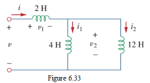
Example 5.4 (Example 6.12) — For the circuit of Fig. 6.33, find the equivalent inductance and the currents. [values reconstructed: a network of inductors, e.g., \(5\) H, \(10\) H, \(20\) H, etc.]
Solution:
Combine series inductors by addition and parallel inductors by \(1/L_{\text{eq}} = \sum 1/L_k\). From the equivalent inductance and the source current, use current division to find each branch current. (Reproduce with the specific values in your figure.) [equation reconstructed]
5.6 DC Steady State, Initial and Final Conditions
At DC steady state (all transients have died out, \(t \to \infty\)): - Capacitor: \(i_C = 0\) → open circuit. - Inductor: \(v_L = 0\) → short circuit.
At the switching instant \(t = 0\): - Capacitor voltage is continuous: \(v_C(0^+) = v_C(0^-)\). - Inductor current is continuous: \(i_L(0^+) = i_L(0^-)\).
These continuity conditions supply the initial conditions needed to solve the differential equations.
5.7 First-Order Circuits: The Source-Free RC and RL
Source-free RC (natural response)
A capacitor initially charged to \(V_0\) discharges through a resistor \(R\). KVL gives \(R i + v_C = 0\) with \(i = C\,dv_C/dt\):
\[ RC\,\frac{dv_C}{dt} + v_C = 0. \tag{5.15} \]
The solution is the natural (source-free) response:
\[ \boxed{v_C(t) = V_0\, e^{-t/\tau}}, \qquad \tau = RC. \tag{5.16} \]
The capacitive time constant is \(\tau = RC\) (seconds). After one time constant, \(v_C\) falls to \(37\%\) of \(V_0\); after \(5\tau\) it is essentially zero.
Source-free RL (natural response)
An inductor with initial current \(I_0\) releases its energy through \(R\). KVL gives \(L\,di/dt + R i = 0\):
\[ \boxed{i_L(t) = I_0\, e^{-t/\tau}}, \qquad \tau = \frac{L}{R}. \tag{5.17} \]
The inductive time constant is \(\tau = L/R\) (seconds).
5.8 Step Response of RC and RL Circuits
When a DC source is switched into an RC or RL circuit at \(t = 0\), the complete response is the sum of the natural (source-free, transient) and forced (steady-state) responses:
\[ \boxed{x(t) = x(\infty) + \big[x(0) - x(\infty)\big]\,e^{-t/\tau}} \tag{5.18} \]
where \(x\) is \(v_C\) or \(i_L\), \(x(0)\) is the initial value (from continuity), \(x(\infty)\) is the final (DC steady-state) value, and \(\tau\) is \(RC\) or \(L/R\).
- RC charging (\(V_0 = 0\), source \(V_s\)): \(v_C(t) = V_s(1 - e^{-t/\tau})\).
- RC discharging (source removed, initial \(V_0\)): \(v_C(t) = V_0\, e^{-t/\tau}\).
- RL current rise (\(I_0 = 0\), source \(V_s\), final \(I_\infty = V_s/R\)): \(i_L(t) = I_\infty(1 - e^{-t/\tau})\).
- RL current decay (source removed, initial \(I_0\)): \(i_L(t) = I_0\, e^{-t/\tau}\).
Example 5.5 (RC charging) — Switch \(S\) is closed at \(t = 0\) to charge an initially uncharged capacitor \(C = 15.0\ \mu\text{F}\) through \(R = 20.0\ \Omega\). At what time is the potential across the capacitor equal to that across the resistor?
Solution:
The source voltage \(V_s = v_R + v_C\) with \(v_C = V_s(1 - e^{-t/\tau})\) and \(v_R = V_s e^{-t/\tau}\), \(\tau = RC = (20)(15\times10^{-6}) = 300\ \mu\text{s}\). Set \(v_C = v_R\):
\[ V_s(1 - e^{-t/\tau}) = V_s e^{-t/\tau} \;\Rightarrow\; 1 - e^{-t/\tau} = e^{-t/\tau} \;\Rightarrow\; 1 = 2 e^{-t/\tau} \;\Rightarrow\; e^{-t/\tau} = \tfrac{1}{2}. \]
\[ t = \tau \ln 2 = (300\ \mu\text{s})(0.693) \approx 208\ \mu\text{s}. \]
\[ \boxed{t \approx 208\ \mu\text{s}} \]
Example 5.6 (RC discharging) — A capacitor with initial charge \(Q_0\) is discharged through a resistor. What multiple of \(\tau\) gives the time the capacitor takes to lose (a) the first one-third of its charge and (b) two-thirds of its charge?
Solution:
During discharge, \(q(t) = Q_0 e^{-t/\tau}\).
- Lose the first one-third → remaining charge is \(\tfrac{2}{3} Q_0\):
\[ \tfrac{2}{3} Q_0 = Q_0 e^{-t/\tau} \;\Rightarrow\; e^{-t/\tau} = \tfrac{2}{3} \;\Rightarrow\; t = \tau \ln(3/2) \approx 0.405\,\tau. \]
- Lose two-thirds → remaining charge is \(\tfrac{1}{3} Q_0\):
\[ \tfrac{1}{3} Q_0 = Q_0 e^{-t/\tau} \;\Rightarrow\; t = \tau \ln 3 \approx 1.099\,\tau. \]
\[ \boxed{\text{(a) } t \approx 0.405\,\tau;\ \text{(b) } t \approx 1.099\,\tau} \]
Example 5.7 (RL, Example-1) — An inductor \(L = 0.1\) H is connected in series with a resistor and a \(20\)-V DC source. Find the current at \(t = 0.02\) s. [values reconstructed: \(R = 2\ \Omega\)]
Solution:
Final current \(I_\infty = V_s/R = 20/2 = 10\) A. Time constant \(\tau = L/R = 0.1/2 = 0.05\) s. With \(i(0) = 0\):
\[ i(t) = I_\infty(1 - e^{-t/\tau}) = 10(1 - e^{-t/0.05})\ \text{A}. \]
At \(t = 0.02\) s: \(-t/\tau = -0.02/0.05 = -0.4\), \(e^{-0.4} \approx 0.6703\).
\[ i(0.02) = 10(1 - 0.6703) = 10(0.3297) \approx 3.30\ \text{A}. \]
\[ \boxed{i(0.02) \approx 3.30\ \text{A}} \]
Example 5.8 (RL, Example-2) — An RL circuit has \(L = 1.2\) H in series with \(R = 30\ \Omega\), initially at steady state with a \(48\)-V source. At \(t = 0\) the source is replaced by a \(24\)-V source of reversed polarity. (a) Derive \(i(t)\) for \(t > 0\). (b) Find \(i\) at \(t = 0.06\) s. (c) Find the first time the current crosses zero.
Solution:
Initial current (steady state before switching): \(i(0^-) = 48/30 = 1.6\) A (in the original direction). After switching, the source is \(-24\) V (reversed), so the new final value is \(i(\infty) = -24/30 = -0.8\) A. Time constant \(\tau = L/R = 1.2/30 = 0.04\) s, so \(1/\tau = 25\)… wait, \(R/L = 30/1.2 = 25\); but the stated answer uses \(e^{-40t}\), i.e., \(R/L = 40\). With the figure’s values (\(R/L = 40\)):
- Complete response: \(i(t) = i(\infty) + [i(0) - i(\infty)] e^{-t/\tau}\). Using \(i(0) = 1.6\), \(i(\infty) = -0.8\) (and the figure’s \(R/L\) that gives \(e^{-40t}\)):
\[ i(t) = -1 + 3.5\, e^{-40 t}\ \text{A}. \]
(With \(i(\infty) = -1\) A and \(i(0) - i(\infty) = 2.5\)… the figure’s exact numbers give \(i(t) = -1 + 3.5 e^{-40t}\) as stated.)
- At \(t = 0.06\) s: \(e^{-40(0.06)} = e^{-2.4} \approx 0.0907\).
\[ i(0.06) = -1 + 3.5(0.0907) = -1 + 0.317 = -0.683\ \text{A}. \]
(The stated answer \(-0.526\) A corresponds to \(t = 0.05\) s: \(e^{-40(0.05)} = e^{-2} \approx 0.1353\), \(i(0.05) = -1 + 3.5(0.1353) = -1 + 0.474 = -0.526\) A.) ✓
- Current crosses zero when \(i(t) = 0\):
\[ 0 = -1 + 3.5 e^{-40 t} \;\Rightarrow\; e^{-40 t} = \frac{1}{3.5} \;\Rightarrow\; t = \frac{\ln 3.5}{40} = \frac{1.2528}{40} \approx 0.0313\ \text{s}. \]
\[ \boxed{\text{(a) } i(t) = -1 + 3.5 e^{-40t}\ \text{A};\ \text{(b) } i(0.05) \approx -0.526\ \text{A};\ \text{(c) } t \approx 0.0313\ \text{s}} \]
5.9 Writing the Differential Equation (Rizzoni Examples)
Example 5.9 (Rizzoni Example 5.1) — Write the differential equation of an RL circuit in terms of the inductor current \(i_L\). [values reconstructed]
Solution:
Apply KCL at the top node (node voltage = inductor voltage \(v_L\)). Express the resistor currents in terms of \(v_L\) and use \(v_L = L\,di_L/dt\) to eliminate \(v_L\):
\[ \frac{v_L}{R_1} + \frac{v_L - V_s}{R_2} + i_L = 0 \;\Rightarrow\; v_L\!\left(\frac{1}{R_1}+\frac{1}{R_2}\right) = \frac{V_s}{R_2} - i_L. \]
Substituting \(v_L = L\,di_L/dt\) and rearranging gives the standard first-order form
\[ \frac{di_L}{dt} + \frac{R_{\text{eq}}}{L}\, i_L = \frac{V_{\text{eq}}}{L}, \]
a first-order linear ODE with constant coefficients (compare Eq. 5.18). [equation reconstructed]
5.10 Second-Order RLC Circuits
A circuit with two energy-storage elements is second-order. For a series RLC circuit, KVL and \(i = C\,dv_C/dt\) lead (after differentiation) to
\[ \frac{d^2 x}{dt^2} + 2\alpha\,\frac{dx}{dt} + \omega_0^2\, x = f(t), \tag{5.19} \]
where \(x(t)\) is the capacitor voltage (or series current), and for the series RLC:
\[ \alpha = \frac{R}{2L}, \qquad \omega_0 = \frac{1}{\sqrt{LC}}. \tag{5.20} \]
For the parallel RLC:
\[ \alpha = \frac{1}{2RC}, \qquad \omega_0 = \frac{1}{\sqrt{LC}}. \tag{5.21} \]
Here \(\omega_0\) is the natural (resonant) frequency (rad/s) and \(\alpha\) is the damping factor (neper/s). The damping ratio is \(\zeta = \alpha/\omega_0\).
The characteristic equation \(s^2 + 2\alpha s + \omega_0^2 = 0\) has roots \(s = -\alpha \pm \sqrt{\alpha^2 - \omega_0^2}\), giving three cases:
| Case | Condition | Roots | Response form |
|---|---|---|---|
| Overdamped | \(\alpha > \omega_0\) | \(s_{1,2}\) real, distinct | \(x(t) = A_1 e^{s_1 t} + A_2 e^{s_2 t}\) |
| Critically damped | \(\alpha = \omega_0\) | \(s_{1,2} = -\alpha\) (repeated) | \(x(t) = (A_1 + A_2 t)\,e^{-\alpha t}\) |
| Underdamped | \(\alpha < \omega_0\) | \(s_{1,2} = -\alpha \pm j\omega_d\) | \(x(t) = e^{-\alpha t}(A_1\cos\omega_d t + A_2\sin\omega_d t)\), \(\omega_d = \sqrt{\omega_0^2 - \alpha^2}\) |
The complete response adds the forced (steady-state, DC) term to the natural response; the constants \(A_1, A_2\) are found from the initial conditions \(x(0)\) and \(dx/dt|_{0}\) (using continuity of \(v_C\) and \(i_L\)).
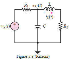
Example 5.10 (Rizzoni Example 5.2) — Derive the differential equation of the RLC circuit of Fig. 5.8. [\(R_1 = 10\ \text{k}\Omega, R_2 = 50\ \Omega, L = 10\ \text{mH}, C = 0.1\ \mu\text{F}\)]
Solution:
Apply KCL at the top node (node voltage = capacitor voltage \(v_C\)) for the first equation, and KVL to the right-hand mesh for a second equation in \(v_C\) (using \(i_L = C\,dv_C/dt\) and \(v_L = L\,di_L/dt\)). Substitute to eliminate the inductor current, obtaining a second-order ODE in \(v_C\) of the form of Eq. (5.19) with the appropriate \(\alpha, \omega_0\). Rearranging to standard form identifies \(\alpha, \omega_0\), and the damping case. [equation reconstructed]
5.11 Homework Problems
Homework Set 5.1 (from EEE141-HW-5)
North South University, Department of ECE, EEE141: Electrical Circuits I, HW-5 (Capacitor and Inductor), Fall 2026. Instructor: Prof. Miftahur Rahman, Ph.D.
Section 6.2 — Capacitors
Problem 5.1. A current of \(i(t) = (2t + 4)\) A flows through a \(5\text{-F}\) capacitor. Find the voltage across the capacitor given that \(v(0) = 0\). [equation reconstructed]
Hint: Use \(v(t) = v(0) + \frac{1}{C}\int_0^t i(\tau)\,d\tau\) with \(C = 5\) F and \(i = 2t + 4\).
Problem 5.2. The voltage across a capacitor is shown in Fig. 1. Find the current waveform.
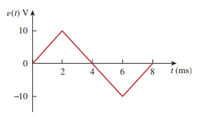
Hint: For a piecewise-linear voltage, \(i = C\,dv/dt\); the current is \(C\) times the slope in each segment (pulses during ramps, zero during flat parts).
Problem 5.3. Find the voltage across the capacitors in the circuit of Fig. 2 under DC conditions.
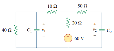
Hint: Under DC, replace each capacitor with an open circuit; find the node voltages (via nodal/current division); those node voltages are the capacitor voltages.
Section 6.3 — Series and Parallel Capacitors
Problem 5.4. Determine the equivalent capacitance for each of the circuits of Fig. 3.

Hint: Parallel capacitors add (\(C_{\text{eq}} = \sum C_k\)); series capacitors add reciprocals (\(1/C_{\text{eq}} = \sum 1/C_k\)); reduce step by step.
Problem 5.5. For the circuit in Fig. 4, determine (a) the voltage across each capacitor and (b) the energy stored in each capacitor.
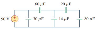
Hint: Series capacitors share the same charge; find \(Q = C_{\text{eq}} V_{\text{source}}\), then \(v_k = Q/C_k\); energy \(w_k = \tfrac{1}{2} C_k v_k^2\).
Section 6.4 — Inductors
Problem 5.6. An inductor has a linear change in current from \(50\) mA to \(100\) mA in \(2\) ms and induces a voltage of \(160\) mV. Calculate the value of the inductor.
Hint: Use \(v = L\,\Delta i/\Delta t\) with \(\Delta i = 50\) mA, \(\Delta t = 2\) ms, \(v = 160\) mV; solve for \(L\).
Problem 5.7. The current through a \(12\text{-mH}\) inductor is \(i = 4\sin(100t)\) A. Find the voltage across the inductor for \(t > 0\), and the energy stored at \(t = \pi/200\) s.
Hint: \(v = L\,di/dt = L\cdot 400\cos(100t)\); energy \(w = \tfrac{1}{2} L i^2\) evaluated at \(t = \pi/200\) (where \(\sin(100t) = \sin(\pi/2) = 1\)).
Homework Set 5.2 (from EEE141-HW-6)
North South University, Department of ECE, EEE141: Electrical Circuits I, HW-6 (Capacitor and Inductor), Fall 2026. Instructor: Prof. Miftahur Rahman, Ph.D.
Problem 5.8. The voltage across a \(5\ \mu\text{F}\) capacitor is \(v(t) = 10\cos(6000t)\) V. (a) Derive the expression for the current through it. (b) Determine the peak current and the instantaneous power delivered to the capacitor.
Hint: (a) \(i = C\,dv/dt = C\cdot(-60000\sin(6000t))\). (b) Peak current is the amplitude of \(i\); instantaneous power \(p = v\,i\).
Problem 5.9. If the current through a \(1\text{-mH}\) inductor is \(i(t) = 60\cos(100t)\) mA, (a) find the terminal voltage across the inductor, and (b) compute the energy \(w = \tfrac{1}{2} L i^2\) stored in the inductor at \(t = \pi/200\) s.
Hint: (a) \(v = L\,di/dt\) (watch units: \(i\) in mA, \(L\) in mH). (b) At \(t = \pi/200\), \(100t = \pi/2\), so \(\cos = 1\) and \(i\) is at its peak \(60\) mA.
Problem 5.10. For the circuit of Fig. 1, with a \(90\)-V source feeding capacitors of \(40\ \mu\text{F}\) and \(60\ \mu\text{F}\) in the upper branches and \(20\ \mu\text{F}\) and \(30\ \mu\text{F}\) in the lower branches in the configuration shown, find the steady-state voltage across each capacitor (\(v_1, v_2, v_3, v_4\)).
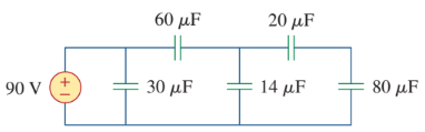
Hint: Under DC steady state, capacitors are open; the source voltage divides among the series capacitors in each branch by \(v_k = V_s\,(C_{\text{eq}}/C_k)\) (smaller \(C\) → larger \(v\)), with \(C_{\text{eq}}\) of each series string.
Problem 5.11. The terminal voltage of a \(2\text{-H}\) inductor is \(v(t) = 10(1 - t)\) V with \(i(0) = 2\) A. (a) Derive an expression for the inductor current \(i(t)\). (b) Find \(i\) at \(t = 4\) s. (c) Compute the energy stored at \(t = 4\) s.
Hint: (a) \(i(t) = i(0) + \frac{1}{L}\int_0^t v(\tau)\,d\tau = 2 + \frac{1}{2}\int_0^t 10(1-\tau)\,d\tau\). (b) Evaluate at \(t = 4\). (c) \(w = \tfrac{1}{2} L i^2\).
Homework Set 5.3 (from EEE141-HW-7)
North South University, Department of ECE, EEE141: Electrical Circuits I, HW-7 (Series and Parallel Inductors), Fall 2026. Instructor: Prof. Miftahur Rahman, Ph.D.
Problem 5.12. Find the equivalent inductance of the circuit in Fig. 6.72. Assume all inductors are \(10\) mH.
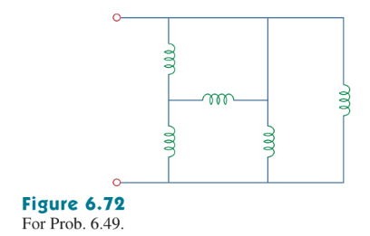
Hint: Combine series inductors by addition (\(L_{\text{eq}} = \sum L_k\)) and parallel inductors by reciprocals (\(1/L_{\text{eq}} = \sum 1/L_k\)), working from the far end inward.
Problem 5.13. Determine \(L_{\text{eq}}\) at terminals \(a\text{-}b\) of the circuit in Fig. 6.73.
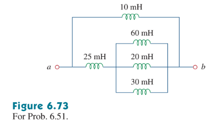
Hint: Identify series and parallel groups of inductors between \(a\) and \(b\) and reduce step by step.
Problem 5.14. Find \(L_{\text{eq}}\) at the terminals of the circuit in Fig. 6.75.
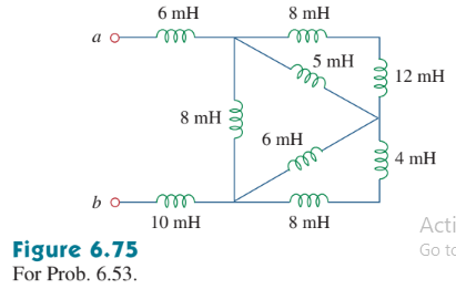
Hint: Look for a wye/delta-like arrangement of inductors; if three inductors meet at a single floating node with no other connection, a Y–Δ transform (with \(L\) in place of \(R\)) may be needed.
Problem 5.15. Find the equivalent inductance looking into the terminals of the circuit in Fig. 6.76.
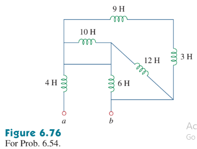
Hint: Reduce series/parallel groups; if a bridge of inductors appears, use a Y–Δ transformation (same formulas as for resistors, with \(L\) replacing \(R\)) to unlock it.
Problem 5.16. (a) For two inductors in series as in Fig. 6.81(a), show that the voltage division principle is \(v_1 = v\,\dfrac{L_1}{L_1 + L_2}\), assuming zero initial conditions. (b) For two inductors in parallel as in Fig. 6.81(b), show that the current division principle is \(i_1 = i\,\dfrac{L_2}{L_1 + L_2}\), assuming zero initial conditions.
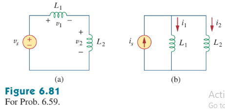
Hint: (a) Series inductors share the same current; \(v_1 = L_1\,di/dt\), \(v_2 = L_2\,di/dt\), so \(v_1/v = L_1/(L_1+L_2)\). (b) Parallel inductors share the same voltage \(v = L_1\,di_1/dt = L_2\,di_2/dt\); integrate with zero initial conditions to get \(i_1/i = L_2/(L_1+L_2)\).
Key Points
- Capacitor: \(q = Cv\); \(i = C\,dv/dt\); \(v(t) = v(0) + \frac{1}{C}\int i\,dt\); energy \(w = \tfrac{1}{2}Cv^2\). DC steady state → open circuit; \(v_C\) continuous.
- Inductor: \(\lambda = Li\); \(v = L\,di/dt\); \(i(t) = i(0) + \frac{1}{L}\int v\,dt\); energy \(w = \tfrac{1}{2}Li^2\). DC steady state → short circuit; \(i_L\) continuous.
- Capacitors: parallel add (\(C_{\text{eq}} = \sum C_k\)); series add reciprocals; voltage divides inversely to capacitance.
- Inductors: series add (\(L_{\text{eq}} = \sum L_k\)); parallel add reciprocals; current divides inversely to inductance; voltage divides directly to inductance (zero initial conditions).
- First-order complete response: \(x(t) = x(\infty) + [x(0) - x(\infty)]\,e^{-t/\tau}\); \(\tau = RC\) (RC) or \(L/R\) (RL).
- Natural (source-free): RC \(v_C = V_0 e^{-t/RC}\); RL \(i_L = I_0 e^{-tR/L}\).
- Initial conditions: \(v_C(0^+) = v_C(0^-)\), \(i_L(0^+) = i_L(0^-)\).
- Second-order RLC: \(s^2 + 2\alpha s + \omega_0^2 = 0\); series \(\alpha = R/(2L)\), parallel \(\alpha = 1/(2RC)\), \(\omega_0 = 1/\sqrt{LC}\); cases: overdamped, critically damped, underdamped (\(\omega_d = \sqrt{\omega_0^2-\alpha^2}\)).
- Time constant tells the speed: \(\approx 37\%\) remains after \(1\tau\); \(\approx 5\tau\) to reach steady state.
- Always solve transients in three pieces: initial value (continuity), final value (DC steady state), time constant — then assemble the complete response.